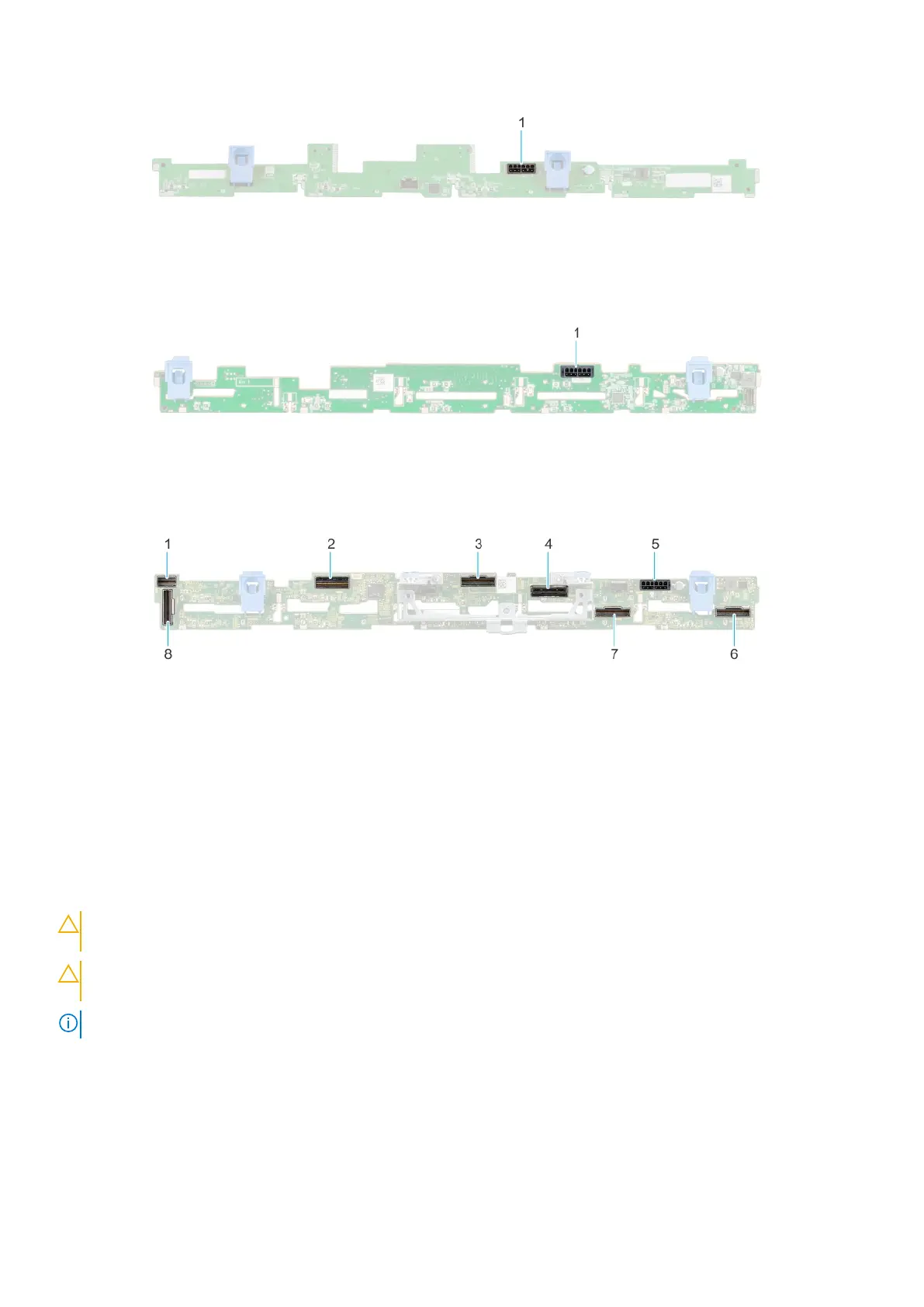
Figure 39. 4 x 3.5-inch drive backplane
1. BP_PWR_1 (backplane power and signal cable to system board)
Figure 40. 8 x 2.5-inch drive backplane
1. BP_PWR_1 (backplane power and signal cable to system board)
Figure 41. 10 x 2.5-inch drive backplane
1.
DST_SA2 (backplane to front PERC) 2. DST_PB2 (PCIe/NVMe connector)
3. DST_PA2 (PCIe/NVMe connector) 4. DST_SA1 (PERC to backplane)
5. BP_PWR_1 (backplane power and signal cable to system
board)
6. DST_PA1 (PCIe/NVMe connector)
7. DST_PB1 (PCIe/NVMe connector) 8. DST_PA3 (PCIe/NVMe connector)
Removing the drive backplane
Prerequisites
CAUTION:
To prevent damage to the drives and backplane, remove the drives from the system before removing
the backplane.
CAUTION: Note the number of each drive and temporarily label them before you remove the drive so that you
can reinstall them in the same location.
NOTE: The procedure to remove the backplane is similar for all backplane configurations.
1. Follow the safety guidelines listed in the Safety instructions.
2. Follow the procedure listed in the Before working inside your system.
3. If installed, remove the air shroud.
4. Remove the drive backplane cover.
5. Remove all the drives.
Installing and removing system components
49
 Loading...