NOTE: Liquid detection cable must be placed underneath the cooling tubes to ensure it does not interfere with the PCIe
risers
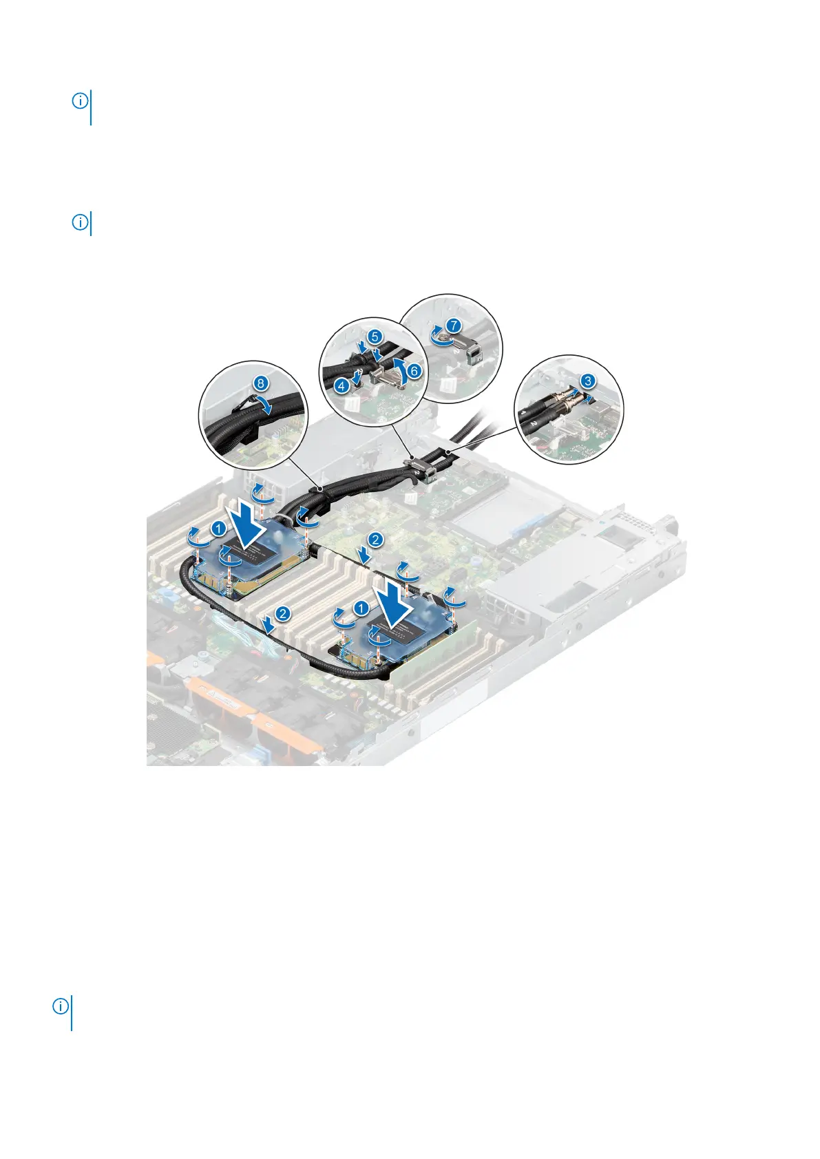
3. Route the liquid cooling tubes through the rear exit point next to the I/O function panel. Ensure the routing follows the
numbered labels on the tube and liquid cooling ring holder (1, 2).
4. Connect the liquid cooling detection cable to the RIO connector.
5. Insert the rubber rings on the tubes on to the rubber holder.
NOTE: The numbers on the image do not depict the exact steps. The numbers are for representation of sequence.
6. Using a Phillips #1 screwdriver, tighten the captive screw on the liquid cooling ring holder to secure it in place.
7. Route the liquid cooling tubes and liquid cooling detection cable along side PSU 2 and secure them with the tube clip.
Figure 79. Installing the liquid cooling heat sink modules
Next steps
1. Remove liquid cooling riser 3.
2. Install the air shroud.
3. Install the system cover.
4. Follow the procedure listed in the After working inside your system.
Expansion cards and expansion card risers
NOTE:
A system event entry is logged in the iDRAC Lifecycle Controller if an expansion card riser is not supported or
missing. It does not prevent your system from turning on. However, if a F1/F2 pause occurs with an error message,
82 Installing and removing system components
 Loading...