NOTE: The number of screws varies depending on the configuration ordered.
2. Lift the heat sink from the system board.
Installing the UMA heat sink
CAUTION: The information in this section is intended for authorized service technicians only.
Prerequisites
If you are replacing a component, remove the existing component before performing the installation process.
About this task
NOTE: If either the system board or the heat sink is replaced, use the thermal grease provided in the kit to ensure that
thermal conductivity is achieved.
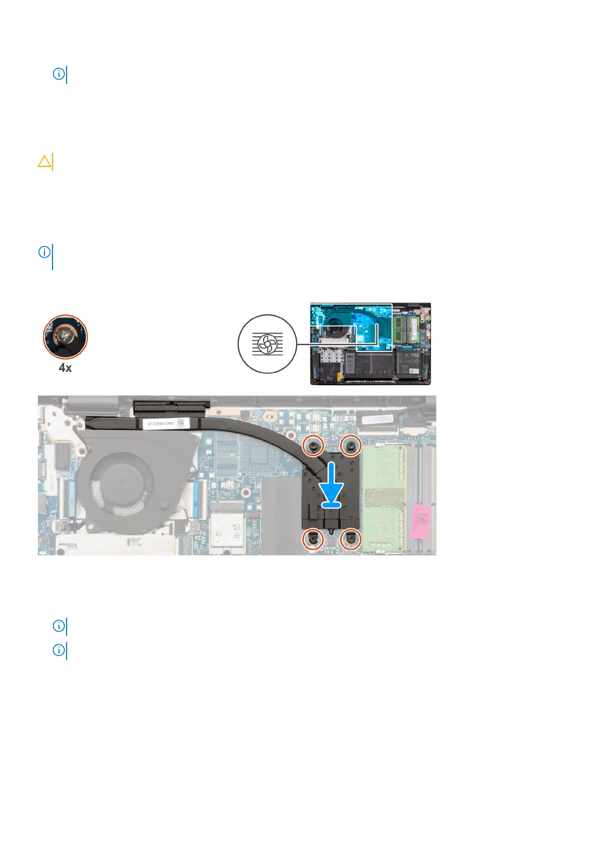
The following images indicate the location of the heat sink and provide a visual representation of the installation procedure.
Steps
1. Place the heat sink on the system board.
2. Tighten the four (M2x2) captive screws that secure the heat sink to the system board.
NOTE: Tighten the captive screws in the sequential order mentioned on the heat sink [1 > 2 > 3 > 4].
NOTE: The number of screws varies depending on the configuration ordered.
Next steps
1. Install the base cover.
2. Install the SD card.
3. Follow the procedure in After working inside your computer.
72
Removing and installing Field Replaceable Units (FRUs)

 Loading...