Steps
1. Remove the two screws (M2.5x5.5) that secure the left display-assembly hinge to the system board.
2. Pry open the left display-assembly hinge at an angle of 90 degrees.
3. Peel the tape that secures the display-cable latch to its connector.
4. Pry open the latch and disconnect the display-assembly cable from its connector on the system board.
5. Remove the two screws (M2.5x5.5) that secure the right display-assembly hinge to the system board.
6. Open the right display-assembly hinge at an angle of 90 degrees.
7. At an angle, gently lift the palm-rest and keyboard assembly off the display assembly.
Installing the display assembly
CAUTION: The information in this section is intended for authorized service technicians only.
Prerequisites
If you are replacing a component, remove the existing component before performing the installation process.
About this task
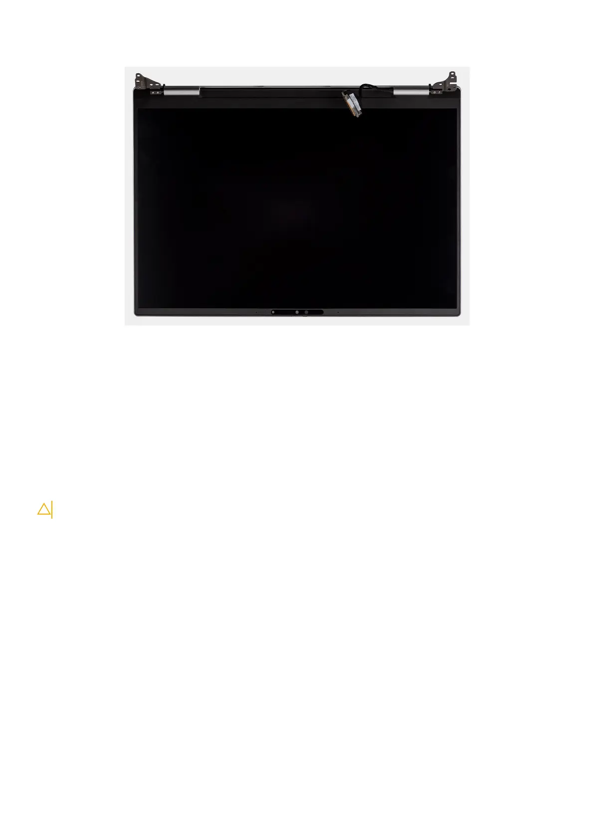
The following image(s) indicate the location of the display assembly and provides a visual representation of the installation
procedure.
Removing and installing Field Replaceable Units (FRUs)
59
 Loading...