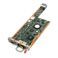
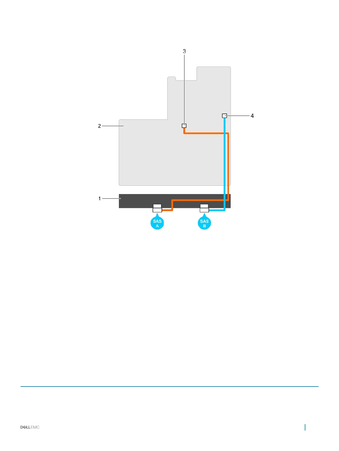
Figure 1. Cabling the S140 controller
1
backplane 2 system board
3 connector on the rst AHCI device (J_SATA A) 4 connector on the second AHCI device (J_SATA B)
Disk connectivity for AHCI devices
The S140 controller supports systems with up to two AHCI devices. For systems with two AHCI devices, the rst AHCI device connects
the drives from ports 0–5 and the second AHCI device connects the drives from ports 6–13.
The following table provides information about the disks connectivity to the AHCI devices supported on the 14th generation PowerEdge
systems.
Table 7. Disk connectivity for AHCI devices
Chipset Platform AHCI device 1 AHCI device 2
Intel C621 (C620 series
chipset)
PowerEdge R640, R740, R740xd, R940, and C6420 0-5 6-13
Cabling the drives for S140 19
 Loading...