About this task
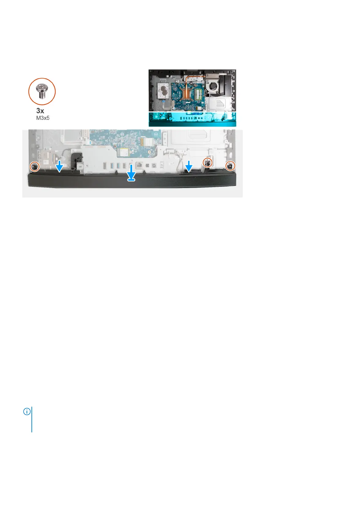
The following image(s) indicate the location of the bottom cover and provides a visual representation of the installation
procedure.
Steps
1. Place and align the bottom cover with the display-assembly base.
2. Align the screw holes on the bottom cover with the screw holes on the display-assembly base.
3. Replace the three screws (M3x5) that secure the bottom cover to the display-assembly base.
Next steps
1. Install the I/O cover.
2. Install the system-board shield.
3. Install the back cover.
4. Install the stand.
5. Follow the procedure in After working inside your computer.
Retractable-camera assembly
Removing the retractable-camera assembly
Prerequisites
1. Follow the procedure in Before working inside your computer.
2. Remove the stand.
3. Remove the back cover.
4. Remove the system-board shield.
About this task
NOTE:
The retractable-camera assembly consists of the following components:
● camera
● microphones
The following image(s) indicate the location of the retractable-camera assembly and provides a visual representation of the
removal procedure.
Removal and installation procedures for Energy Efficient processors
127
 Loading...