4. Route the antenna cables through the routing guides on the display-assembly base and the power-supply fan.
5. Route the audio-board cable through the routing guides on the display-assembly base and the power-supply fan.
6. Thread the power-supply fan cable under the I/O bracket and route the power-supply fan cable through the routing guide on
the display-assembly base.
7. Connect the power-supply fan cable (FAN SYS) to the system board.
Next steps
1. Install the bottom cover. .
2. Install the power-supply unit.
3. Install the I/O cover.
4. Install the system-board shield.
5. Install the back cover.
6. Install the stand.
7. Follow the procedure in After working inside your computer.
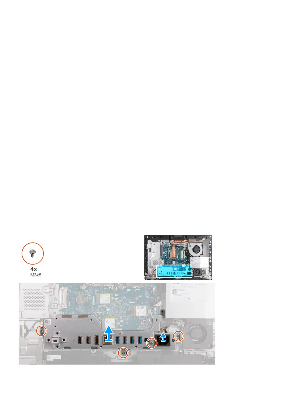
I/O bracket
Removing the I/O bracket
Prerequisites
1. Follow the procedure in Before working inside your computer.
2. Remove the stand.
3. Remove the back cover.
4. Remove the system-board shield.
5. Remove the I/O cover.
6. Remove the bottom cover.
About this task
The following image(s) indicate the location of the I/O bracket and provides a visual representation of the removal procedure.
82
Removal and installation procedures for High Performance processors
 Loading...