Steps
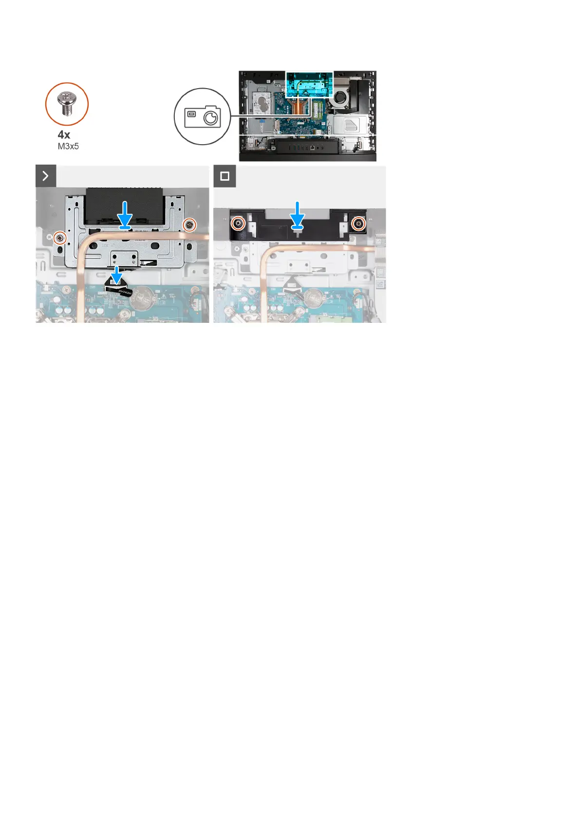
1. Slide the retractable-camera assembly under the heat sink into its slot on the display-assembly base.
2. Align the screw holes on the retractable-camera assembly with the screw holes on the display-assembly base.
3. Replace the two screws (M3x5) that secure the retractable-camera assembly to the display-assembly base.
4. Connect the camera cable (WEBCAM) to the system board.
5. Place the camera-assembly bracket over retractable-camera assembly.
6. Align the screw holes on the camera-assembly bracket with the screw holes on the display-assembly base.
7. Replace the two screws (M3x5) that secure the camera-assembly bracket to the display-assembly base.
Next steps
1. Install the system-board shield.
2. Install the back cover.
3. Install the stand.
4. Follow the procedure in After working inside your computer.
Fan
Removing the fan
Prerequisites
1. Follow the procedure in Before working inside your computer.
2. Remove the stand.
3. Remove the back cover.
4. Remove the system-board shield.
About this task
The following image(s) indicate the location of the fan and provides a visual representation of the removal procedure.
Removal and installation procedures for Energy Efficient processors
129
 Loading...