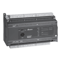
1 Analog Input Module DVP04AD-E2
1.8 Applications
1.8.1 Measuring Current
1.
Description
Assume there is an equipment that requires PLC to convert the external current -20mA ~ 20mA supplied
into digital signals and display the value in register D0 for monitoring the current.
Set the input signals of the A/D module as mode 4, i.e. the current input mode (-20mA ~ +20mA).
2. Devices
D40: average value of the input signals
D50: present value of the input signal
D0: actual value of the present measured current
3. Wiring
Connect the current signal to be measured to CH1 of DVP04AD-E2 and short-circuit V+ and I+ (as shown
below).
104.7K
250
-20mA~+20mA
V1+
I1+
VI1+
CH1
104.7K
AG
FE
CH1
Current Input
Shieled cable
4. Program explanation
When PLC goes from STOP to RUN, set CH1 as current input mode 4 (-20mA ~ +20mA) (CR#2), and
together set the average times of the input signals in CH1 as 10 (CR#8).
Save the average value of the input signals measured into D40 and the present value of the input signal
measured into D50.
In the current mode of DVP04AD-E2, the value range -20mA ~ 20mA corresponds to K-32,000 ~ K32,000.
D50 is 1600 times of the actual current value (i.e. 32,000/20 = 1,600). Divide the value in D50 by 1,600 and
store the value obtained into D0 which will be the actual value of the present measured current.
5. Program example
Ladder diagram: Explanation:
Set CH1 as mode 4 (current input mode)
Set the average times of CH1 as 10
Store the average value of CH1 input signals
into D40
Store the present value of CH1 input signal
into D50
M1002
M1000
K0 K1TO
D9900 D40
K0
K20 K1
K0
K1TO
K1600
FROM
DIV
K4
K10
D50 D0
K2
K8
MOV
D50
D50/1600 = D0 (the actual value of the
present measured current in CH1)
DVP-ES2 Module Manual
1-17

 Loading...