3 Mixed Analog Input/Output Module DVP06XA-E2
VO1
IO1
AG
CH5
CH5
-10V~+10V
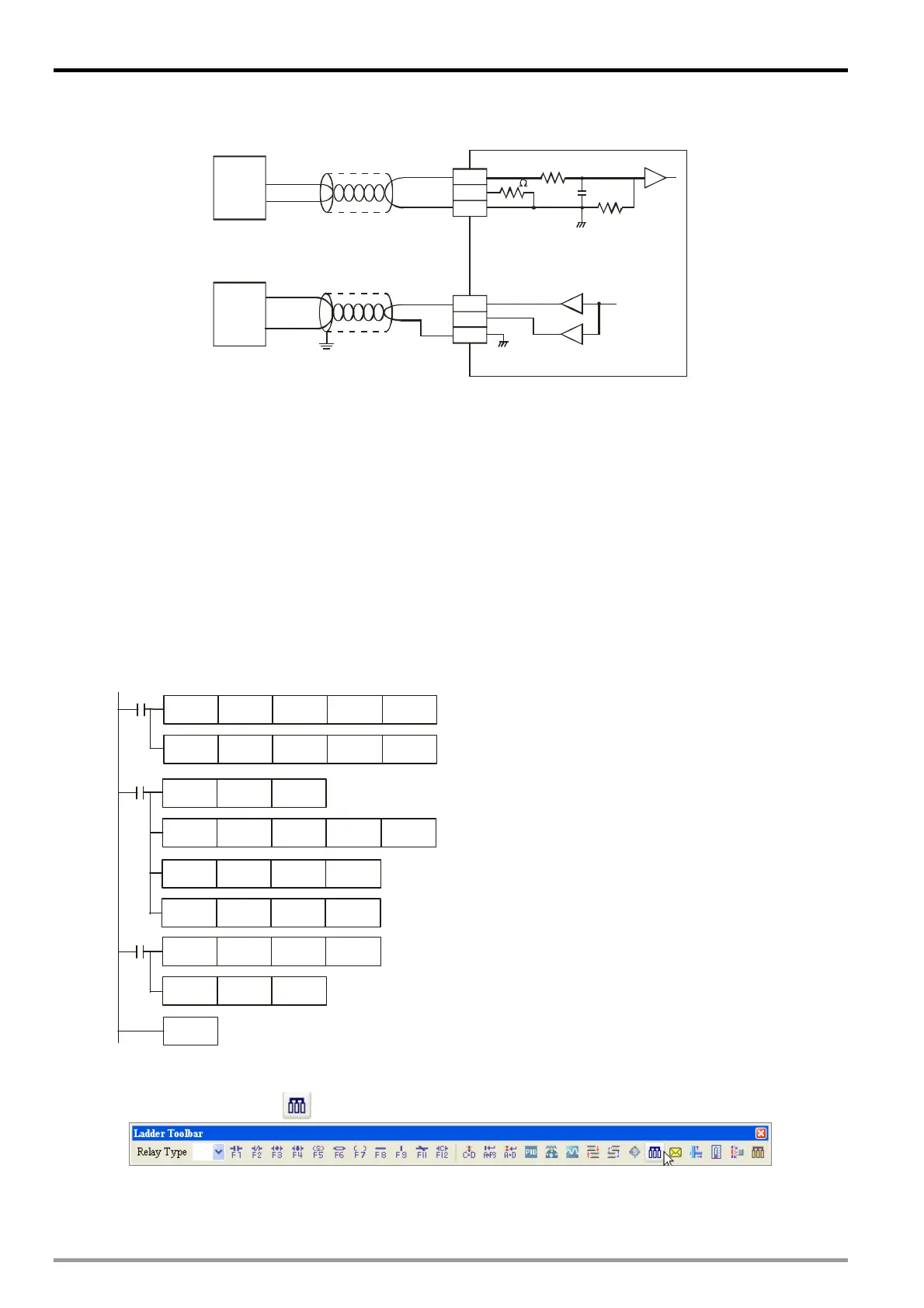
VFD-B
AUI
ACM
CH1
104.7K
250
DC 0V~10V
V1+
I1+
VI1+
CH1
104.7K
AG
AFM
ACM
Shielded cable
*1
Shielded cable
*1
Analog output
of AC motor drive
Model A
Model B
Voltag e outpu t
4. Program explanation
When PLC goes from STOP to RUN, because VFD-B model A offers analog voltage output 0 ~ 10VDC to
06XA, you have to set CH1 as voltage input mode (mode 2) and CH5 as voltage output mode (mode 0).
In addition, set the average times of the input signals at CH1 as 10.
Save the present digital value of the input signal measured into D50.
In the voltage input mode of 06XA, The value range for 0 ~ 10V DC is K0 ~ K32,000. Data in D50 is
3,200 times of the actual voltage value (i.e. 32,000/10 = 3,200). Divide the value in D50 by 3,200 and
store the value obtained into D0 which represents the actual voltage measured.
Frequency range 0 ~ 50.0Hz corresponds to 0 ~ 10V. Multiply the value in D0 with 5 and store the value
obtained into D4 which represents actual frequency value
In the voltage output mode of 06XA, the value range for -10V ~ 10V is K-32,000 ~ K32,000. D4 is the
frequency of VFD-B model A. FWD/REV frequency -50Hz ~ 50Hz corresponds to K-32,000~ K32,000
(32,000/50 = 640). Multiply the value in D4 with 640 and store the digital value obtained into D60 which
represents the corresponding digital value of Ch5 output voltage.
5. Program example
Ladder diagram: Explanation:
Set CH1 as mode 0
Set the average times of CH1 signals as 10
Store the average digital value of CH1 signals
into D40
Store the present digital value of input signals
into D50
D50/3200 = D0, the voltage measured
D0*5 = D4, the output frequency of VFD-B
model A
Multiply D4 with 640 to obtain the output value
of VFD-B Model B.
M1002
M1000
K0 K1TO
K0 K1TO
D0
K5
M1000
END
D9900
K0 K1
D0 K640
D60
D50 K3200
K2 K2
K8 K10
MOV
FROM D50
DIV D0
MUL
D4
MUL
D60
MOV D9904
K20
D40
D60 is the corresponding digital value of Ch5
output voltage.
3.8.2 How to Set the Module Wizard in WPLSoft
1. Open WPLSoft and click on .
DVP-ES2 Module Manual
3-22

 Loading...


