2 Analog Output Module DVP02DA-E2/DVP04DA-E2
5. Program example
Ladder diagram: Explanation:
Set CH1 as mode 1 (current output mode)
Set the Offset value of CH1
Set the Gain value of CH1
X0
M0
X1
K0
K34 K1
K0 K40
K1
K0
K1
TOP
K0
K1
M0
TOP
TOP
TOP
X1
SET
H1
K9600
K20800
H1
K2
K28
Disable CH1 set value changing
2.8 Applications
2.8.1 Analog Current Output
1.
Explanation
Assume there is an equipment that requires PLC to convert the digital signals into current 0mA ~ 20mA
for controlling the equipment through its analog terminals.
Set the output signals of the D/A module as mode 1, i.e. the current output mode (0mA ~ 20mA)
2. Devices
D0: target current output value of CH1
D40: digital value converted corresponding to the target output current of CH1
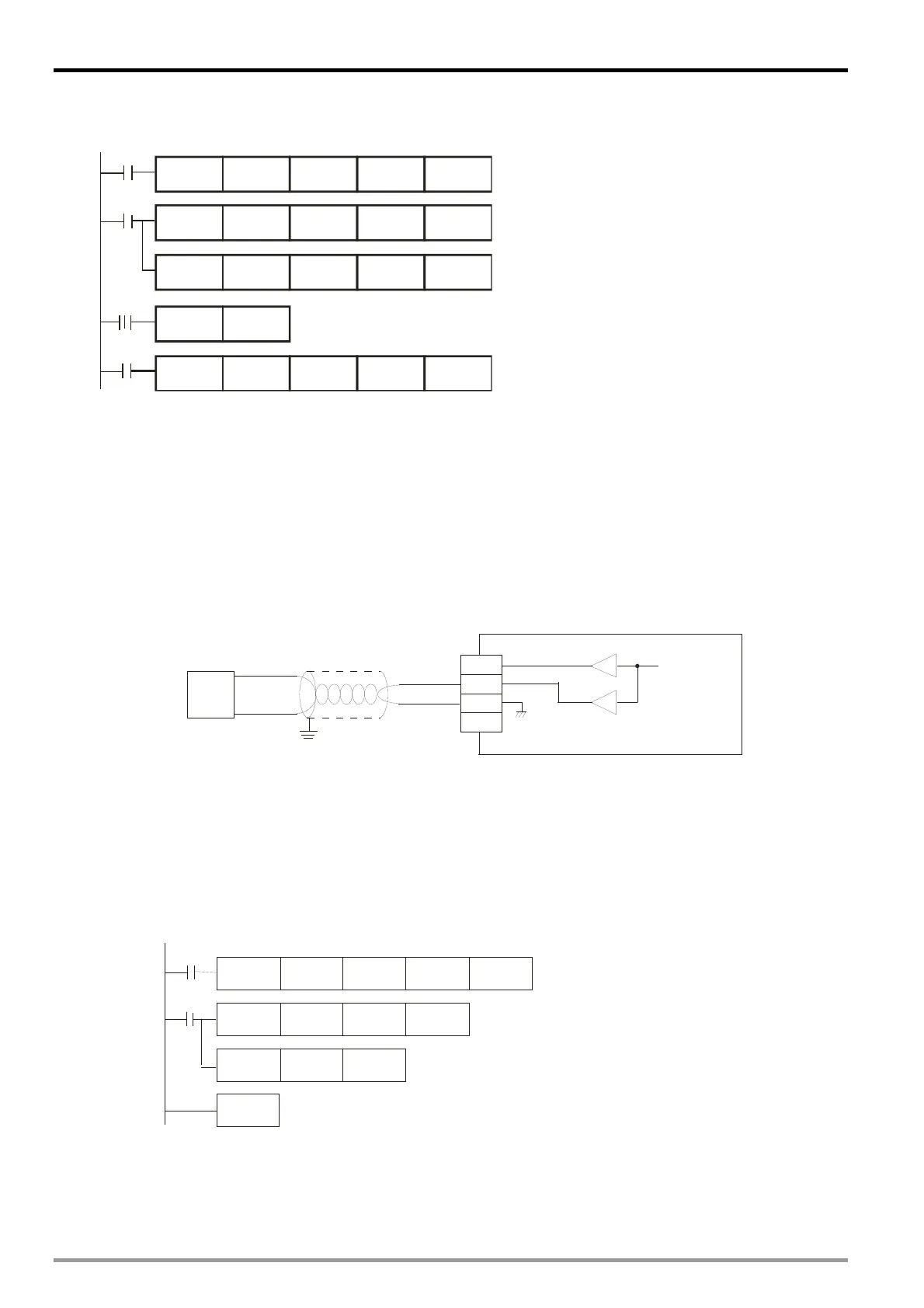
3. Wiring
Connect the analog input terminal on the equipment to CH1 of DVP04DA-E2 (as shown below).
VO1
IO1
AG
FE
0mA~20mA
CH1
CH1
Current output
Shielded cable
AC motor drive,
recorder,
scale valve..
4. Program explanation
When PLC goes from STOP to RUN, set CH1 as current output mode 1(0mA ~ 20mA)
In the current output mode 1, the value range 0 ~ 20mA corresponds to K0 ~ K32,000. D0 is the target
current output value of CH1, which should be multiplied with 1600 (i.e. 20/32,000 = 1/1,600) to obtain the
digital output value. Multiply the value in D0 with 1,600 and store the value obtained into data register
D40 for DVP04DA-E2 to convert the digital value into analog current output.
5. Example program
Ladder diagram: Explanation:
Set CH1 as mode 1 (current output mode)
D0 is the target current output value of CH1
D40 is the corresponding digital value of
target output current specified in D0
M1002
M1000
END
K0
K1TO
D0 K1600
D9900
D40
K2
H1
MUL D40
MOV
DVP-ES2 Module Manual
2-12
 Loading...


