3 Mixed Analog Input/Output Module DVP06XA-E2
DVP-ES2 Module Manual
3-5
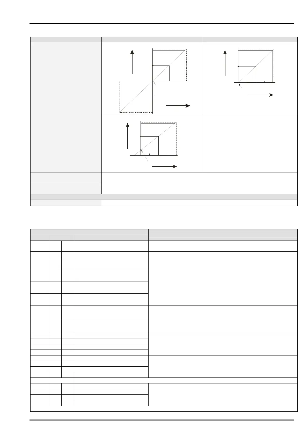
Digital/Analog (D/A) Voltage output Current output
Mode 0 (H’0000): (-10V ~ +10V)
10V
+3 2,000
0
Offset
5V
Gain
+1 6,000
Voltage
output
Digital input
-10 V
-5V
-32 ,0 00
+3 2,767
-32 ,7 68
Mode 1 (H’0001): (0mA ~ +20mA)
20mA
+3 2,000
0
Offset
Gain
+1 6,000
10mA
Current
output
Digita inputl
+3 2,767
D/A conversion curve
(Default: mode 0)
Mode 2 (H’0002): (+4mA ~ +20 mA)
20mA
+3 2,000
0
Offset
4mA
+1 6,000
12mA
Current
outpu t
Digita inputl
Gain
+3 2,767
-6,40 0
Mode -1 (H’FFFF): Channel unavailable.
The channel is disabled. Output voltage = 0;
output current = 0.
Operation/storage
1. Operation: 0°C ~ 55°C (temperature), 50 ~ 95% (humidity), pollution degree 2
2. Storage: -25°C ~ 70°C (temperature), 5 ~ 95% (humidity)
Vibration/shock immunity
International standards: IEC61131-2, IEC 68-2-6 (TEST Fc) / IEC61131-2 & IEC 68-2-27
(TEST Ea)
Power Supply
Max. rated power consumption
24V DC (20.4 ~ 28.8V DC) (-15% ~ +20%), W, supplied by external power source
3.6 CR (Control Register)
3.6.1 CR in DVP06XA-E2
DVP06XA-E2
CR# Attrib. Register content
Description
#0 YES R Model name
Set up by the system:
DVP06XA-ES2 model code = H’00C4
#1 YES R Firmware version Display the current firmware version in hex.
#2 YES R/W CH1 Input mode setting
#3 YES R/W CH2 Input mode setting
#4 YES R/W CH3 Input mode setting
#5 YES R/W CH4 Input mode setting
Input mode: Default = H’0000. Take CH1 for example:
Mode 0 (H’0000): Voltage input (-10V ~ +10V).
Mode 1 (H’0001): Voltage input (-5V ~ +5V).
Mode 2 (H’0002): Voltage input (0V ~ +10V).
Mode 3 (H’0003): Voltage input (0V ~ +5V).
Mode 4 (H’0004): Current input (-20mA ~ +20mA).
Mode 5 (H’0005): Current input (0mA ~ +20mA).
Mode 6 (H’0006): Current input (4mA ~ +20mA).
Mode -1 (H’FFFF): Channel 1 unavailable.
#6 YES R/W CH5 output mode setting
#7 YES R/W CH6 output mode setting
Output mode: Default = H’0000. Take CH5 for example:
Mode 0 (H’0000): Voltage output (-10V ~ +10V).
Mode 1 (H’0001): Current output (0mA ~ +20mA).
Mode 2 (H’0002): Current output (4mA ~ +20mA).
Mode -1 (H’FFFF): Channel 5 unavailable.
#8 YES R/W CH1 average times
#9 YES R/W CH2 average times
#10 YES R/W CH3 average times
#11 YES R/W CH4 average times
Set average times at CH1 ~ CH4:
Range = K1 ~ K100
Default = K10
#12 NO R CH1 average input value
#13 NO R CH2 average input value
#14 NO R CH3 average input value
#15 NO R CH4 average input value
Average value of input signals at CH1 ~ CH4
#18 ~ #19 Reserved
#20 NO R CH1 present input value
#21 NO R CH2 present input value
#22 NO R CH3 present input value
#23 NO R CH4 present input value
Present value of input signals at CH1 ~ CH4
#24 ~ #27 Reserved

 Loading...


