1 Analog Input Module DVP04AD-E2
1.1 The A/D Conversion
In industrial automation, many measuring units are transmitted by analog signals. The most frequently adopted range
for the signals are voltage -10V ~ 10V and current -20mA ~ 20mA. To use the analog signals as the parameters for
PLC operations, you have to convert them into digital values first.
For example, the voltage -10V ~ 10V is first converted into values -32,000 ~ +32,000 by an A/D module, and the PLC
will read/write the control registers (CR) in the A/D module. The signals sent back to the PLC for operations will be
digital K-32,000 ~ K32,000.
1.2 Introduction
DVP04AD-E2 analog signal input module receives external 4 points of analog input signals (voltage or current) and
converts them into 16-bit digital signals. The Main Processing Unit (MPU) can read/write the data in the module by
using FROM/TO instructions or D9900~D9999 in the program. You can select voltage input or current input by the
wiring. Range for voltage input: ±10V (±32,000). Range for current input: ±20mA (±32,000).
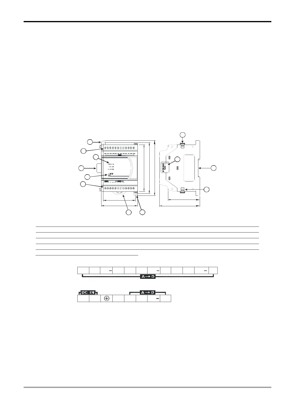
1.3 Product Profile and Outline
1.3.1 DVP04AD-E2
70
62
106
98
78
90
61.5
2
1
4
5
9
6
6
7
7
8
8
3
++ + + + +
+ +
Unit: mm
1. Connection port for extension unit/module 6. Terminals
2. DIN rail (35mm) 7. Mounting hole
3. Model name 8. Fixing clip for extension unit/module
4. POWER, ERROR, AD indicators 9. Mounting port for extension unit/module
5. DIN rail clip
I/O terminals
+
V1
+
I1 FEVI1
+
V2 FEV3VI2I2
+
FE
+
I3
+
VI3
0V24V FE
+
V4 VI4
+
I4 FE
DVP-ES2 Module Manual
1-1

 Loading...


