3 Mixed Analog Input/Output Module DVP06XA-E2
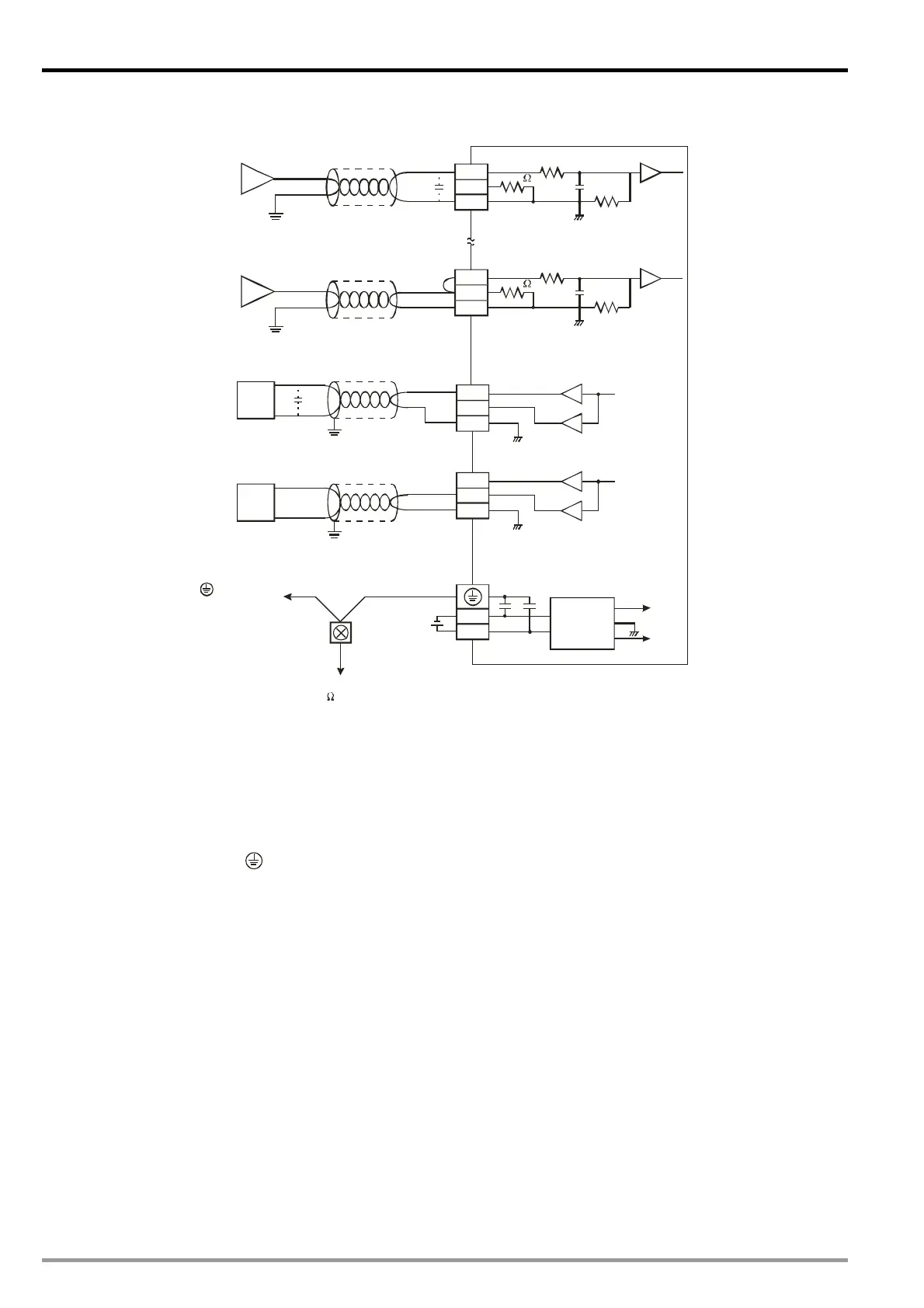
3.4 External Wiring
CH1
104.7K
250
-10V~+10V
V1+
I1+
VI1-
CH1
104.7K
CH4
104.7K
250
-20mA~+20mA
V4+
I4+
VI4-
CH4
104.7K
*3
*2
AG
AG
VO1
IO1
AG
CH5
-10V~+10V
*5
CH5
VO2
IO2
AG
CH6
0mA~20mA
CH6
0V
24V
DC24V
DC/DC
+15V
-15V
AG
Class 3 gr ound in g
(100 or less)
converter
Shielded cable*4
Current input
Current output
Vo lt ag e ou tpu t
Vo lt ag e inp ut
Terminal of
power module
AC motor drive,
recorder,
scale valve...
AC motor drive,
recorder,
scale valve...
Shielded cable*1
Shielded cable*1
Shielded cable*1
*1: When performing analog input, please isolate other power wirings.
*2: When the XA module is connected to current signals, make sure you short-circuit "V+” and “I+” terminals.
*3: If the ripples at the loaded input terminal are too significant that causes noise interference on the wiring,
connect the wiring to 0.1 ~ 0.47F 25V capacitor.
*4: When performing analog output, please isolate other power wirings.
*5: If the ripples at the loaded output terminal are too significant that causes noise interference on the wiring,
connect the wiring to 0.1 ~ 0.47F 25V capacitor.
*6: Please connect the
terminal on both the power module and XA module to the system earth point and
ground the system contact or connect it to the cover of power distribution cabinet.
DVP-ES2 Module Manual
3-2

 Loading...


