3 Mixed Analog Input/Output Module DVP06XA-E2
You only need to set up the D/A conversion curve for once. Set up CR#40 (Set value changing prohibited)
to prevent incorrect operations.
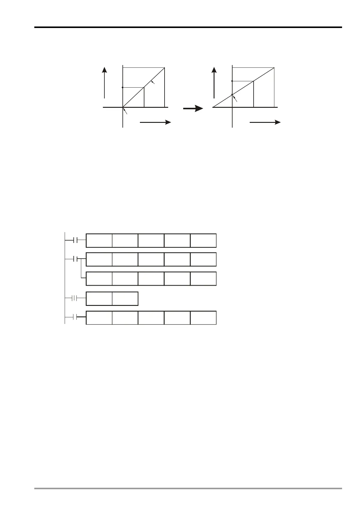
2. Adjusted Curve
20mA
+32,000
0
Offset
10mA
Gain
+16,000
Current
output
Mode 1
Digital input
20mA
+32,000
0
Offset
6mA
Gain
+16,000
Current
output
Digital input
13mA
3. Devices
X0 = On: Set the output mode of the signals at CH6 as mode 1.
X1 = On: Set Offset value of CH6 as 6mA (9,600) and Gain value as 13mA (20,800).
M0 = On: Disable CH6 set value changing
4. Program explanation
When X0 = On, set CR#7 as K1 (H’0001) and the signal output mode at CH6 as mode 1 (current output
mode).
When X1 = On, write K9,600 (Offset value of CH6) into CR#33 and K20,800 (Gain value of CH6) into
CR#39.
When X1 goes from On to Off, set M0 = On to disable the adjustment on D/A conversion curve. Write
K32 (H’20) into CR#40 b5=1 to disable
CH6 set value changing.
5. Program example
Ladder diagram: Explanation:
Set CH6 as mode 1 (current output mode)
Set the Offset value of CH6
Set the Gain value of CH6
X0
M0
X1
K0
K39 K1
K0 K40
K1
K0
K1
TOP
K0
K1
M0
TOP
TOP
TOP
X1
SET
H1
K9600
K20800
H20
K7
K33
Disable CH6 set value changing
3.8 Applications
3.8.1 Speed Tracing of AC Motor Drive
1.
Description
The multi-functional voltage output terminal (AFM) on VFD-B series AC motor drive model A offers
signals of present speed (0 ~ 50Hz) which corresponds to 0 ~ 10V analog output signals to DVP06XA-E2,
and 06XA will then offer analog voltage output to the voltage input terminal (AUI) on VFD-B series AC
motor drive model B, for executing auto speed tracing of the AC motor drive.
Set the input signals of CH1 as mode 2, i.e. the voltage input mode (0V ~ 10V)
Set the output signal of CH5 as mode 0, i.e. the voltage output mode (-10V ~ 10V).
2. Devices
D0: present voltage value measured
D4: frequency of VFD-B model A
D40: average digital value of the input signals at CH1
D50: present digital value of input signal at CH1
D60: corresponding digital value of output voltage at CH5
3. Wiring
Connect the analog voltage output terminal (AFM/ACM) on VFD-B model A to CH1 of DVP06XA-E2 and
connect the analog voltage input terminal (AUI/ACM) on VFD-B model B to CH5 of DVP06XA-E2 (as
shown on the next page).
DVP-ES2 Module Manual
3-21

 Loading...


