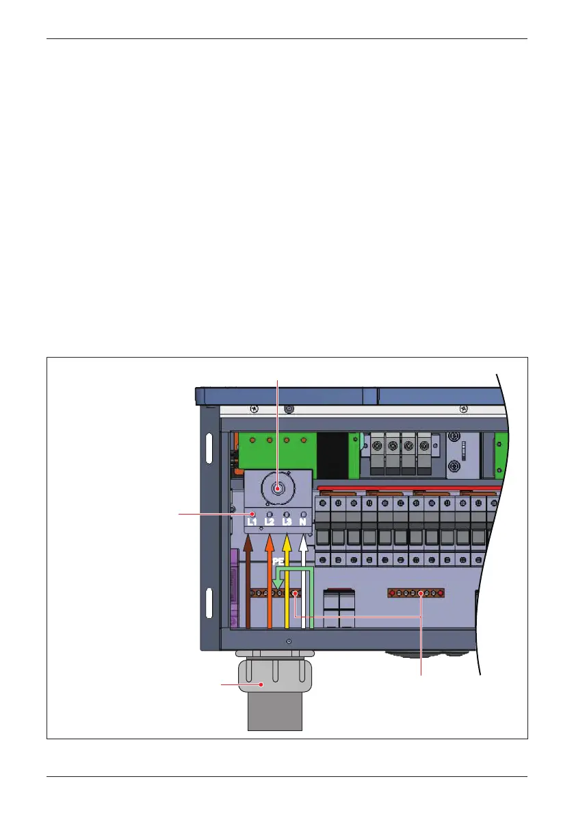
Figure 3-19 illustrates the location of the AC conduit entry and connections and
AC terminal block: for 120 models.
Ensure the AC conductors used are sized to the correct ampacity per NEC or
other local code. Refer to Figure 3-17.
- Open all AC switch cage-clamps as noted in Section 3.3.4.
- Insert stripped phase conductor into appropriate switch terminal.
- Tighten each phase terminal lug to a torque value of 31 lbf-in (3.5 N•m).
- Loosen screw in one of the locations on the ground bar located on the rear wall
of the WB chassis.
- There are two options for connecting the PE conduit to the model 120 inverter:
• Insert the EGC (6~4 AWG) into the ground bar and tighten the lugin the
ground bar lug to a torque value of 26 lbf-in (3 N•m). (see Figure 3-19)
• Insert the EGC (1~2/0 AWG) into the grounding screw terminal, torque value
of 80 lbf-in (9 N•m). (see Figure 3-20)
3.3.5 AC Wiring for M80/60U_120 models
Figure 3-19: Two optional Location of AC terminals and wiring (120 model)
After inserting
conductor, torque
terminal screw to
31 lbf-in (3.5 N•m)
After inserting conductor,
torque terminal screw to 26 lbf-in (3 N•m)
Allowable PE conductor
size 6~4 AWG (14~22mm²)
AC switch
L3L2L1
AC chassis entry accommodates
up to 2" trade size conduit
(e.g., EMT)
EMT
NN
PE
PE
42
Installation
 Loading...


