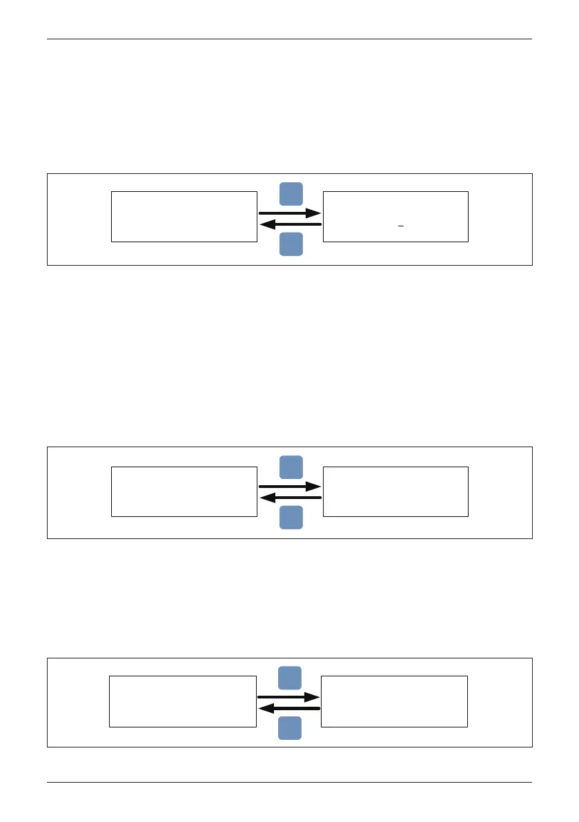
Figure 4-10: Inverter ID screen display
Figure 4-11: Insulation screen display
Inverter ID is the RS-485 address which is assigned to the inverter and used
when the RS-485 communication system is operating, e.g., connected to a PC
or data logger. If several inverters are connected to the RS-485 bus, each must
have a distinct Inverter ID. Allowable ID values are 1-254. Consult data logger
manufacturer to determine maximum number of inverters on a single RS-485 bus.
Prior to connecting to grid, the inverter control will measure the impedance
between the floating PV array(s) and ground (PE), also known as isolation
resistance, RISO. This measurement is compared to an internal limit and used
to determine if any ground fault is present in the array prior to connection of the
inverter to the grid.
The inverter will not connect to the grid if the measured resistance is smaller
than 100kΩ.
4.3.7.1 Inverter ID
4.3.7.2 Insulation
Setting ID:
ID = 0
02
Inverter ID: 1
Insulation
Grid Code
Grid Settings
►
EXIT
ENT
Mode: ON
Resistance: 100kΩ
►
ON
DC1 only
DC2 only
OFF
►
EXIT
ENT
The grid code setting is used to program the inverter control system to be
consistent with the grid voltage, frequency and basic grid configuration of the
country or locale where installed. In NA, the grid code setting is IEEE 1547 480V.
4.3.7.3 Grid Code
Inverter ID: 2
Insulation
Grid Code
Grid Settings
►
►
IEEE1547 480V
IEEE1547.A 480V
HECO A
HECO B
EXIT
ENT
Figure 4-12: Grid Code screens
72
Commissioning
 Loading...


