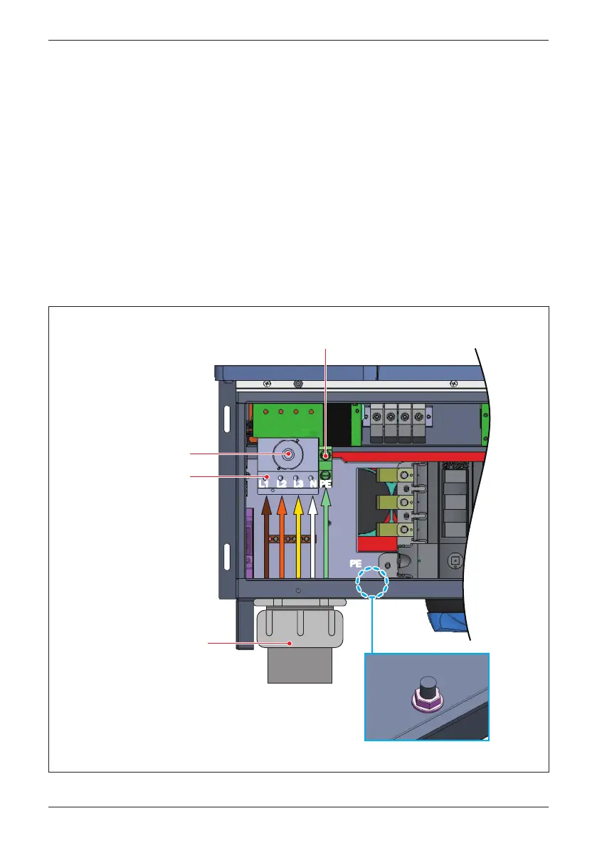
Figure 3-22: Two optional Locations for AC terminal (121 Model Without RSD)
After inserting conductor,
torque terminal screw to 49.5 lbf-in (5.6 N•m)
EMT
Bottom entry option using
2" (max) trade size raceway
After inserting conductor,
torque terminal screw to
31 lbf-in (3.5 N•m)
Refer to Figure 3-17 in Section 3.3 for the procedure to prepare AC conductors
for connection to the AC terminals (M80/60U
_121) :
Ensure the AC conductors used are sized to the correct ampacity per NEC or
other local code. Refer to Figure 3-17.
- Open all AC switch cage-clamps as noted in Section 3.3.4
- Ensure the correct conductor is connected to the appropriate terminal.
- After conductor is inserted, tighten L1~N terminal with a torque value of
31 lbf-in (3.5 N•m), PE terminal with 49.5 lbf-in (5.6 N•m).
- Insert the EGC (1~2/0 AWG) into the grounding screw terminal, torque value
of 80 lbf-in (9 N•m). (see Figure 3-22)
3.3.7
AC Wiring for M80/60U_121 models (Without RSD)
L3L2L1
NN PE
PE
AC switch
After inserting conductor,
torque terminal screw to 80 lbf-in (9 N•m)
Allowable PE conductor size 1~2/0 AWG (35~50mm²)
Grounding screw terminal
PEPE
45
Installation
 Loading...


