Chapter 4 Parameters
VFD-EL-W
4-88
operation increases noise interference. Note that a too large differential causes more noise interference. In
addition, the differential shows the change and the output is 0 when there is no change. Note that you
cannot use the differential control independently. You must use it with the other two controllers for the PD
controller or PID controller.
Sets the D controller gain to determine the error change response. Using a suitable differential time
reduces the P and I controllers overshoot to decrease the oscillation for a stable system. A differential time
that is too long may cause system oscillation.
The differential controller acts on the change in the error and cannot reduce the interference. Do not use
this function when there is significant interference.
10.05 Upper Bound for Integral Control
Unit: 1
Settings
0–100%
Default: 100
Defines an upper bound for the integral gain (I) and therefore limits the Master Frequency. The formula is
Integral upper bound = Maximum Output Frequency (Pr.01.00) x (Pr.10.05).
An excessive integral value causes a slow response due to sudden load changes and may cause motor
stall or machine damage.
10.06
PID Filter Time
Unit: 0.1
Settings 0.0–2.5 sec. Default: 0.0
The output for PID filter time helps reduce the system oscillation.
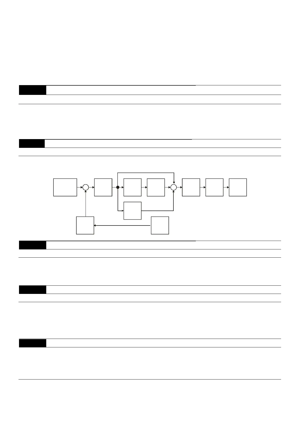
Refer to the following closed-loop control diagram:
P
10.02
I
10.03
D
10.04
10.10
+
-
+
+
+
Setpoint
Input Freq.
Gain
PID
feedback
Integral
gain
limit
Output
Freq.
Limit
Digital
filter
Freq.
Command
10.07
PID Output Frequency Limit
Unit: 1
Settings 0–110 % Default: 100
Defines the percentage of the output frequency as the limit for PID control. The formula is Output
Frequency Limit = Maximum Output Frequency (Pr.01.00) X Pr.10.07%. This parameter limits the
Maximum Output Frequency. You can set an overall limit for the output frequency in Pr.01.07.
10.08
PID Feedback Signal Detection Time Unit: 0.1
Settings 0.0–3600.0 sec. Default: 60.0
This function in only for ACI signal.
Defines the time during which the PID feedback is abnormal before a warning (see Pr.10.09) is given. It
can also be modified according to the system feedback signal time.
If you set it to 0.0, the system does not detect any abnormality signal.
10.09
Erroneous PID Feedback Signal Action
Default: 0
Settings 0 Warn and ramp to stop
1 Warn and coast to stop
2 Warn and keep operating
This function in only for ACI signal.
Determines the AC motor drive action when the feedback signals (analog PID feedback) are abnormal
according to Pr.10.16.