Chapter 4 Parameters
VFD-EL-W
4-45
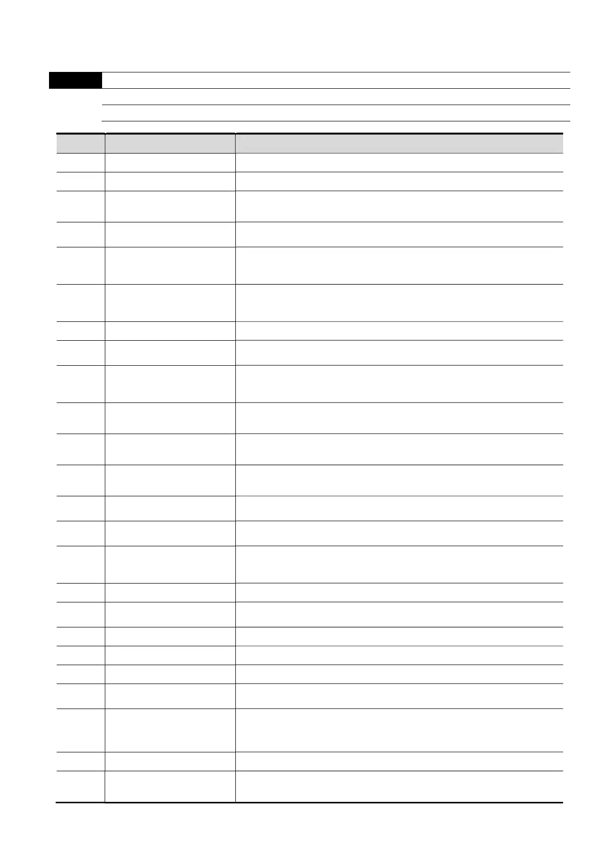
Group 3: Output Function Parameters
You can set this parameter during operation.
03.00
Multi-function Output Relay (RA1, RB1, RC1)
Default: 8
Settings 0–25
Settings
Function Description
0
No Function There is no function for the output terminals.
1 Indication During Run
Active when the drive is ready or RUN command is ON.
2
Indication of Master
Frequency Reached
Active when the AC motor drive reaches the output frequency setting.
3 Zero Speed
Active when Frequency command is lower than the Minimum Output
Frequency.
4 Over-Torque Detection
Active when the drive detects over-torque. Pr.06.04 sets the over-
torque detection level, and Pr.06.05 sets the over-torque detection
time.
5
Base Block (B.B.)
Indication
Active when the output of the AC motor drive is shut off during Base
Block. You can force Base Block with the multi-function input (setting
09).
6 Low-Voltage Indication
Active when low voltage (Lv) is detected.
7 Operation Mode Indication
Active when the operation command is controlled by the external
terminal.
8 Fault Indication
Active when the drive detects abnormal conditions; the contact will be
closed (example: oc, ov, oH1, oL, oL1, EF, cF3.0–5, HPF1, 2, 4, ocA,
ocd, ocn).
9
Desired Frequency
Reached
Active when the desired frequency (Pr.03.02) is reached.
10
Terminal Count Value
Reached
Active when the counter reaches the Terminal Count Value.
11
Preliminary Count Value
Reached
Active when the drive executes the external counter if the count value
is equal to the setting value for Pr.03.06.
12
Over-voltage Stall
Prevention
Active when the Over-voltage Stall Prevention function is operating.
13
Over-current Stall
Prevention
Active when the Over-current Stall Prevention function is operating.
14 IGBT Overheat Warning
When the IGBT overheats, it signals to prevent OH from turning off the
drive. When the temperature is higher than 85
o
C (185
o
F), it is ON.
When it is lower than 80
o
C (180
o
F), it is OFF.
15 Over-voltage
Active when the DC bus voltage exceeds the setting level.
16 PID Feedback Error
Active when the PID feedback signal is abnormal (refer to Pr.10.08 and
Pr.10.12).
17 Forward Command
Active when the direction command is FWD.
18 Reverse Command
Active when the direction command is REV.
19 Zero Speed Output Signal
Active when the drive is in standby or stop.
20 Warning
Active when there is a communication warning (CExx, AoL2, AUE,
FbE, SAvE).
21
Mechanical Brake Control
(Desired Frequency
Reached)
Active when the output frequency Pr.03.11. Deactivated when the
output frequency Pr.03.12 after STOP command.
22 Drive Ready
Active when the drive is on and no abnormality is detected.
23
Multi-pump System Error
Display (Only Master)
If any error occurred on the drive for the multi-pump system, the RLY
outputs.