Chapter 2 Installation and Wiring
VFD-EL-W
2-8
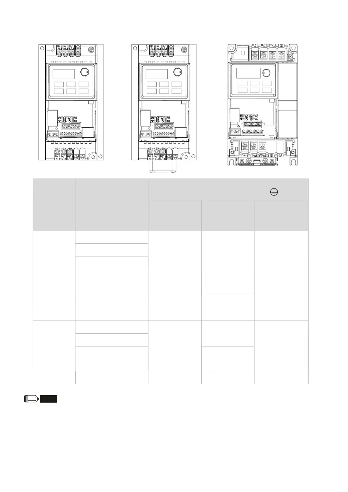
2.3.2 Main Circuit Terminals
Frame A1
Frame A2
Frame B
Frame Model
Main Circuit Terminals
R/L1, S/L2, T/L3,U/T1, V/T2, W/T3,
Maximum
Wire
Gauge
Minimum
Wire
Gauge
Screw Size
Tightening
Torque (±10%)
A1
VFD002EL21W(-1)
4 mm
2
[12 AWG]
2.5 mm
2
[14 AWG]
M4 screw
15 kgf-cm
[13 lbf-in]
[1.47 N-m]
VFD004EL21W(-1)
VFD004EL43W(-1)
VFD007EL21W(-1)
4 mm
2
[12 AWG]
VFD007EL43W(-1)
2.5 mm
2
[14 AWG]
A2 VFD015EL43W(-1)
B
VFD015EL21W(-1)
10 mm
2
[8 AWG]
10 mm
2
[8 AWG]
M4 screw
13 kgf-cm
[11.4 lbf-in]
[1.3 N-m]
VFD022EL21W(-1)
VFD022EL43W(-1)
2.5 mm
2
[14 AWG]
VFD040EL43W(-1)
For installation at an ambient temperature of 50°C, select copper wires with temperature resistance of 75°C or
90°C. For installation at an ambient temperature over 50°C, select copper wires with temperature resistance
of 90°C or above.
For installation of VFD007EL21W(-1) at an ambient temperature of 40°C, select copper wires with temperature
resistance of 75°C or 90°C. For installation at an ambient temperature over 40°C, select copper wires with
temperature resistance of 90°C or above.
When installing VFDxxxEL21W(-1), select wires with voltage rating of 300V
AC
or above. When installing
VFDxxxEL43W(-1), select wires with voltage rating of 600V
AC
or above.