Chapter 4 Parameters
VFD-EL-W
4-47
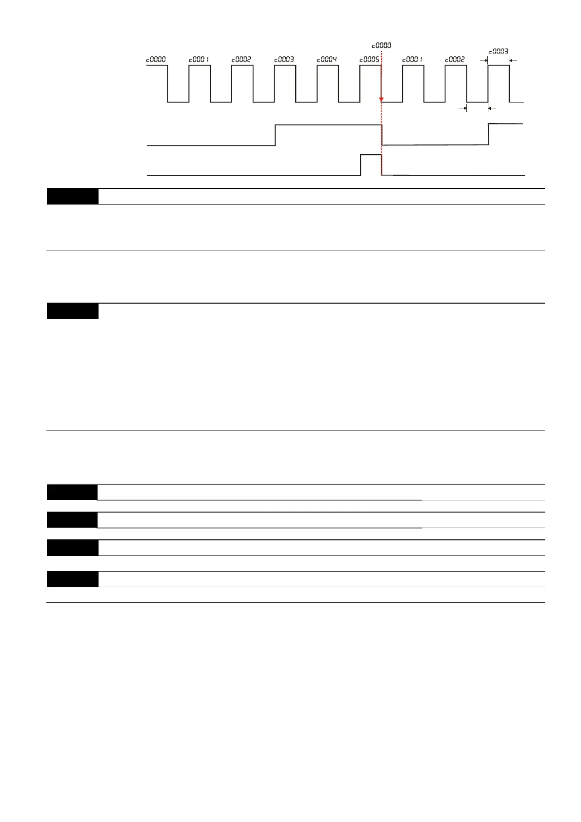
Terminal Count Value
(Pr. 03.00=10)
Preliminary Count Value
(Pr. 03.00=11)
Display
(Pr.00.04=1)
TRG
Counter Trigger
The width of trigger signal
should not be less than
2ms(<250 Hz)
Ex:03.05=5,03.06=3
03.07
EF Active when Terminal Count Value Reached
Default: 0
Settings 0:
Terminal count value reached, no EF display.
1:
Terminal count value reached, EF active.
If you set this parameter to 1 and the desired counter setting value is reached, the AC motor drive treats it as a
fault. The drive stops and shows the “EF” message on the display. The AC motor drive continues to run until
you press RESET.
03.08
Fan Control
Default: 0
Settings 0:
Fan is always ON.
1:
One minute after the AC motor drive stops, the fan is OFF.
2:
Fan is ON when the AC motor drive runs, fan is OFF when the AC motor drive
stops.
3:
4:
Fan is ON when the preliminary heat sink temperature is reached.
Fan is ON when the AC motor drive runs; fan is OFF when the AC motor drive
stops. And the fan is in a standby mode at 0 Hz.
Determines the operation mode of the cooling fan.
This parameter is only valid for fan cooling models. The 1 HP models have no fans (convective cooling) so this
parameter cannot be used for 1 HP models.
03.09
Reserved
03.10
Reserved
03.11
Mechanical Brake Release Frequency Unit: 0.01
Settings 0.00–20.00 Hz Default: 0.00
03.12
Mechanical Brake Engage Frequency Unit: 0.01
Settings 0.00–20.00 Hz Default: 0.00
These two parameters set control of the mechanical brake through the output terminals (Relay) by setting
Pr.03.00 to 21. Refer to the following example for details.
Example:
1. Case 1: Pr.03.12 Pr.03.11
2. Case 2: Pr.03.12 Pr.03.11