Chapter 2 Installation and Wiring
VFD-EL-W
2-9
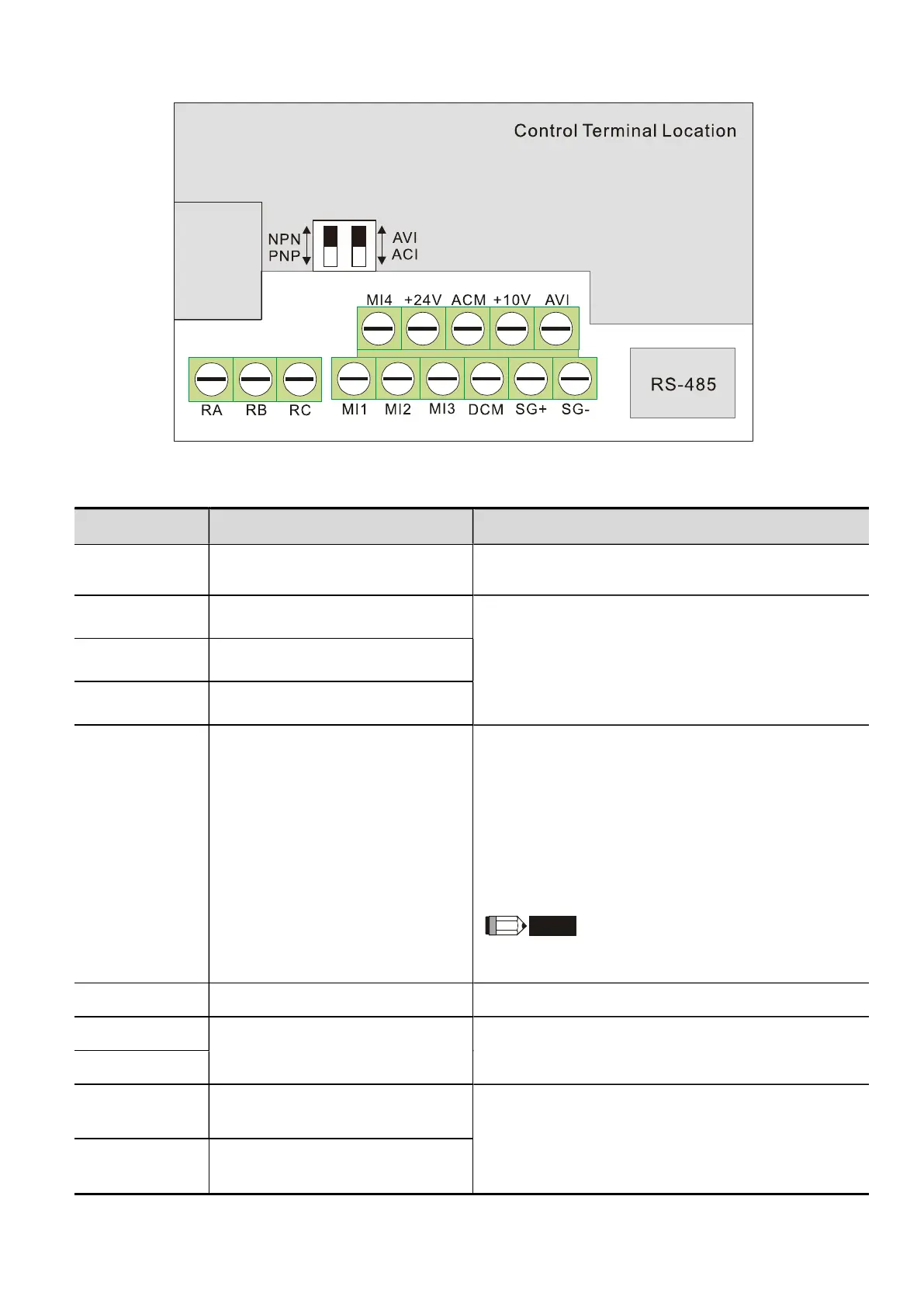
2.4 Control Terminals
Terminal symbols and functions
Terminal Symbol
Terminal Function Defaults (NPN mode) ON: Connect to DCM
MI1 Run-Stop Command
ON: Run in MI1 direction
OFF: Stop acc. to Stop Method
MI2 Multi-function Input 2
Refer to Pr.04.06 to Pr.04.08 for programming the
multi-function inputs.
ON: the activation current is 5.5 mA.
OFF: leakage current tolerance is 10 μA.
MI3 Multi-function Input 3
MI4 Multi-function Input 4
+24V DC Voltage Source
The common terminal is only used for a multi-function
input terminal.
Output voltage: 23–25V, load capacity: 20 mA
+24V terminal is only used for digital control signal
common when in the internal power supply PNP mode.
(Or used for digital control signal common when in the
external power supply NPN mode.)
For detailed wiring instructions, refer to NPN and PNP
mode description.
Do not use the +24V terminal for other external power
loads to avoid damage to the hardware circuit.
DCM Digital Signal Common (Sink) Common for multi-function input terminals.
SG+
Modbus RS-485
Internally connected to RJ45 terminal PIN5 and PIN4,
providing flexible choice for users (only support one
them at one time).
SG-
RA Multi-function Relay Output (N.O.) a
Resistive Load:
5A (N.O.) / 3A (N.C.) 240 V
AC
5A (N.O.) / 3A (N.C.) 24 V
DC
Inductive Load:
RB Multi-function Relay Output (N.C.) b