Chapter 5 Parameters_VFD-B Series
5-64
Revision 10/2005, BE13, SW V4.08
04 - 10
Digital Terminal Input Debouncing Time Unit: 2
Settings 1 to 20 Factory Setting: 1
This parameter is to delay the signals on digital input terminals. 1 unit is 2 msec, 2 units are 4 msec, etc. The
delay time is to debounce noisy signals that could cause the digital terminals to malfunction.
04 - 23
Gear Ratio for Simple Index Function Unit: 1
Settings 4 ~ 1000 Factory Setting: 200
04 - 24
Index Angle for Simple Index Function Unit: 0.1
Settings
0.0 ~360.0¡
Factory Setting: 180.0
04 - 25
Deceleration Time for Simple Index Function Unit: 0.01
Settings 0.00 ~100.00 sec Factory Setting: 0.00
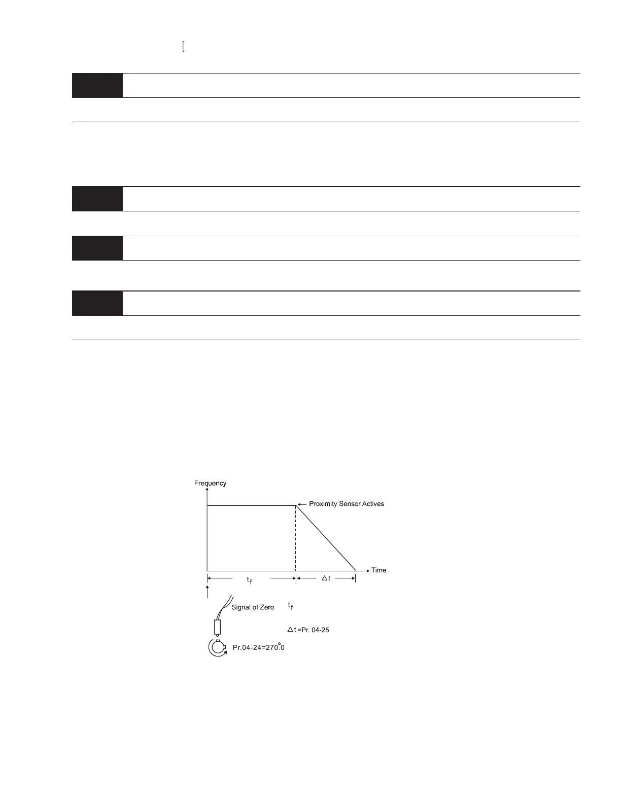
The simple index function is used to position the machine/motor at the same position when it stops. The
function should be used with setting 34 for Multi-Function Input Terminals (04-04 to 04-09).
The function diagram is shown below. The machine is driven by a gear motor or other reduction gearbox.
The trigger position of the proximity sensor is used as the starting point of the index angle. When the stop
command is initiated, the AC motor drive will not decelerate until the proximity sensor is triggered. After that
the AC motor drive begins to decelerate and stop according to the Pr.04-24 and Pr.04-25.
time between STOP and triggering by proximity
sensor. It depends on the moment the STOP
command is given.
 Loading...