Chapter 2 Installation and Wiring_VFD-B Series
2-22
Revision 10/2005, BE13, SW V4.08
Terminal symbols and functions
Terminal Symbol Terminal Function
Factory Settings (SINK)
ON: Connect to DCM
FWD Forward-Stop command
ON: Run in FWD direction
OFF: Stop acc. to Stop Method
REV Reverse-Stop command
ON: Run in REV direction
OFF: Stop acc. to Stop Method
JOG Jog command
ON: JOG operation
OFF: Stop acc. to Stop Method
EF External fault
ON: External Fault. Display “EF”
and stop acc. To Stop
Method.
OFF: No fault
TRG External counter input
ON: At every pulse counter is
advanced by 1.
MI1 Multi-function Input 1
MI2 Multi-function Input 2
MI3 Multi-function Input 3
MI4 Multi-function Input 4
MI5 Multi-function Input 5
MI6 Multi-function Input 6
Refer to Pr.04-04 to Pr.04-09 for
programming the Multi-function
Inputs.
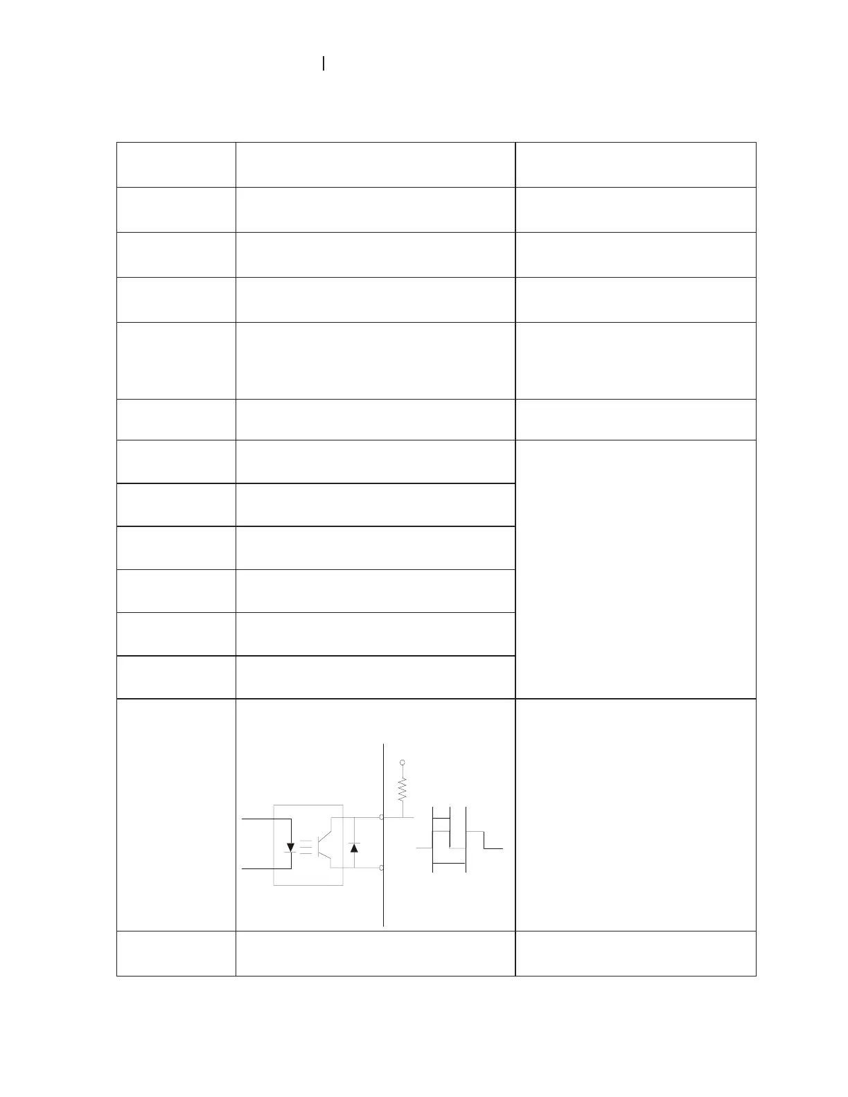
DFM
Digital Frequency Meter
(Open Collector Output)
Max: 48V
50mA
DFM-DCM
100%
50%
Internal Circuit
Pulse voltage output monitor signal,
proportional to output frequency
Duty-cycle: 50%
Ratio: Pr.03-07
Min. load: 10Kȍ
Max. current: 50mA
Max. voltage: 48VDC.
+24V DC Voltage Source
+24VDC, 20mA
used for SOURCE mode.
 Loading...