Chapter 5 Parameters_VFD-B Series
Revision 10/2005, BE13, SW V4.08 5-101
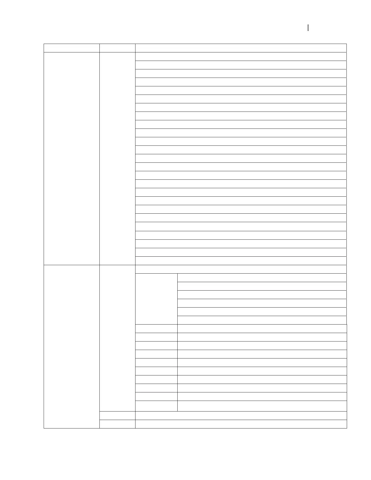
Content Address Function
02: Over-voltage (ov)
03: Overheat (oH)
04: Overload (oL)
05: Overload1 (oL1)
06: External fault (EF)
07: IGBT short circuit protection (occ)
08: CPU failure (cF3)
09: Hardware protection failure (HPF)
10: Current exceeds 2 times rated current during accel (ocA)
2100H
11: Current exceeds 2 times rated current during decel (ocd)
12: Current exceeds 2 times rated current during steady state operation (ocn)
13: Ground Fault (GFF)
14: Low voltage (Lv)
15: CPU failure 1 (cF1)
16: CPU failure 2 (cF2)
17: Base Block
18: Overload (oL2)
19: Auto accel/decel failure (cFA)
20: Software protection enabled (codE)
21: EF1 Emergency stop
22: PHL (Phase-Loss)
23: cEF (Preliminary count value attained, EF active)
24: Lc (Under-current)
25: AnLEr (Analog feedback signal error)
Status monitor
Read only
26: PGErr (PG feedback signal error)
Status of AC drive
LED: 0: light off, 1: light up
00: RUN LED
01: STOP LED
02: JOG LED
03: FWD LED
2101H
Bit 0-4
04: REV LED
Bit 5 0: F light off, 1: F light on
Bit 6 0: H light off, 1: H light on
Bit 7 0: “u” light off, 1: “u” light on
Bit 8 1: Master frequency Controlled by communication interface
Bit 9 1: Master frequency controlled by analog signal
Bit 10 1: Operation command controlled by communication interface
Bit 11 1: Parameters have been locked
Bit 12 0: AC drive stops, 1: AC drive operates
Bit 13 1: Jog command
Bit 14-15 Reserved
2102H Frequency command (F)
2103H Output frequency (H)
 Loading...