16
IP2251EN
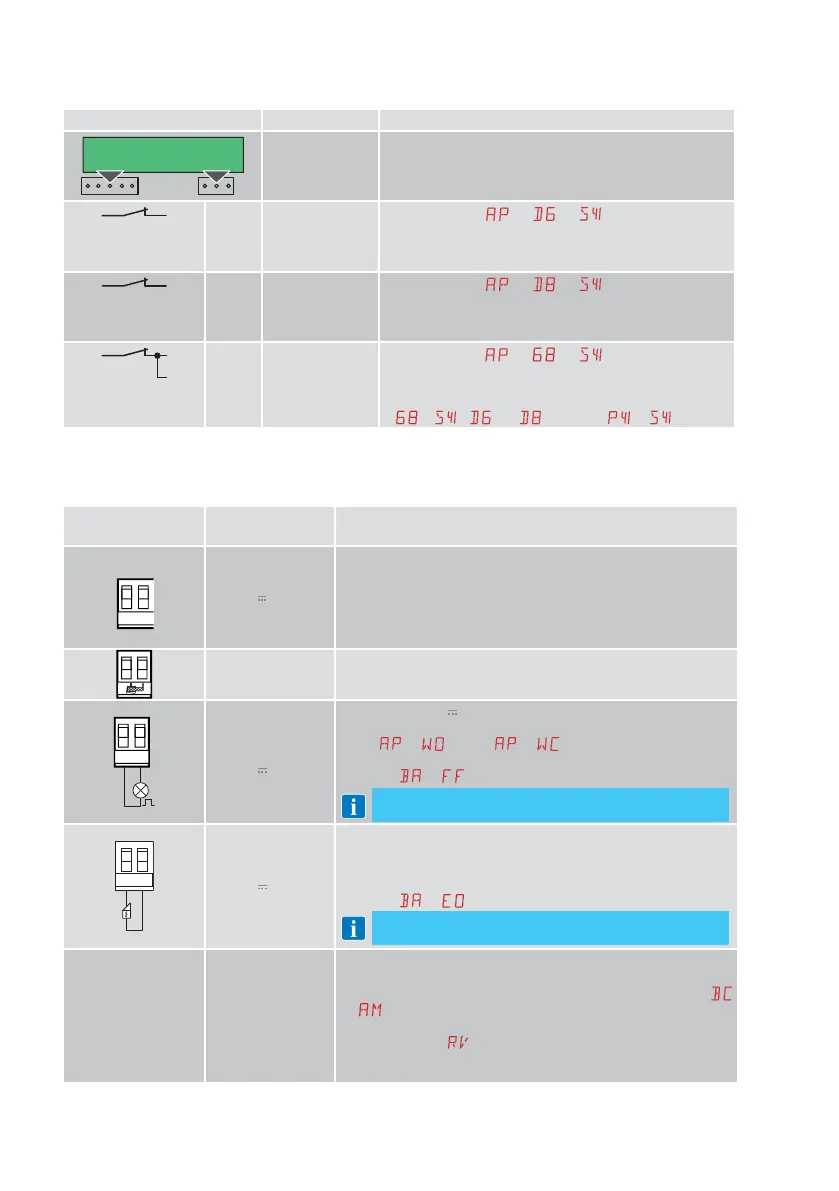
8.1 SOFA1-SOFA2 or GOPAVRS self-controlled safety edge
Command Function Description
GOPAV
SOFA1-SOFA2
SAFETY TEST
Insert the SOFA1-SOFA2 or GOPAVRS device in the slot
for plug-in boards AUX1 or AUX2.
If the test fails, an alarm message appears on the display.
1
6
NC SAFETY STOP
When selecting
→ → , connect the output
contact of the safety device to terminals 1-6 on the con-
trol panel (in series with the photocell output contact, if
installed).
1
8
NC
CLOSURE SAFE-
TY DEVICE
When selecting
→ → , connect the output
contact of the safety device to terminals 1-8 on the con-
trol panel (in series with the photocell output contact, if
installed).
1
6
8
NC
CLOSING/OPEN-
ING SAFETY
DEVICE
When selecting
→ → , connect the output
contact of the safety device to terminals 1-6-8 on the
control panel (in series with the photocell output contact,
if installed).
If
→ , and cannot be or .
9. Outputs and accessories
Output
Value of
accessories
Description
0
-
1
+
24V / 0.3A
Power supply to accessories.
Output for power supply to external accessories.
NOTE: the maximum absorption of 0.3A corresponds to the sum
of all terminals 1.
The gate open indicator light (1-13) is not calculated in the 0.3 A
indicated above, the maximum value considered is 3 W.
GOL148REA
If the GOL868R4 radio receiver is used (868.35MHz), connect the
supplied antenna wire (90mm).
+LP-
FL24
24V
/ 25W
Configurable 24V
output (default: flashing)
The pre-flashing settings can be selected from the third level
menu
→ and/or → .
To modify the operating mode of the LP output, refer to the
selection
→ .
NOTE: compatible with 12/24 V~ electric locks
-+LK
24V / 15W
Electric lock
It is activated when the operation begins with the automation
closed.
To modify the operating mode of the LK output, refer to the
selection
→ .
NOTE: compatible with 12/24 V~ electric locks
AUX
SOFA1 – SOFA2
GOPAVRS
LAB9
BIXR2
BIXPR2
LAN7S
MOBCRE
The control panel has two slots for plug-in command and safety
boards.
The action of the control card can be defined by selecting
→
.
When using slot-in radio boards, remove the RDX module. The
display will show
.
Warning: the plug-in board must be inserted and removed with
the power supply disconnected.
 Loading...


