DE08TS Diesel Engines Major Maintenance
a. Rotate the crankshaft to overlap the intake and the
exhaust valves of #6, then #1 cylinder become the
compression state of top dead center.
b. Therefore adjust the valve clearance corresponding
to
““
of lower figure.
At this time there are no force on the push rods of
#1 cylinder.
c. Rotating the crankshaft by one revolution, #6 cylin-
der become the compression state of top dead cen-
ter.
d. Thereafter adjust the valve clearances correspond-
ing to
““
of lower figure.
e. After reinsuring the valve clearances, retighten if
necessary.
Cylinder compression pressure
1. Stop the engine after warming up, and take out noz-
zle holder assembly.
2. Install the special tool (compression gauge
adapter) at the nozzle holder hole, and connect the
compression pressure gauge there.
* Condition : Water temperature 20°C, Engine rotation
200rpm (10 rotations)
EFM1004I
16
123456
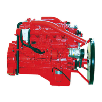
Intake valve Exhaust valve Cylinder no. Cooling fanFlywheel
EA9O5005
Standard value 28kg/cm
2
over
Limit value 24kg/cm
2
Difference
Within
L
10 %
between each cylinder
• No. 1 cylinder is located at the side where flywheel was installed.
 Loading...