Page 18
614-09354-01_EN
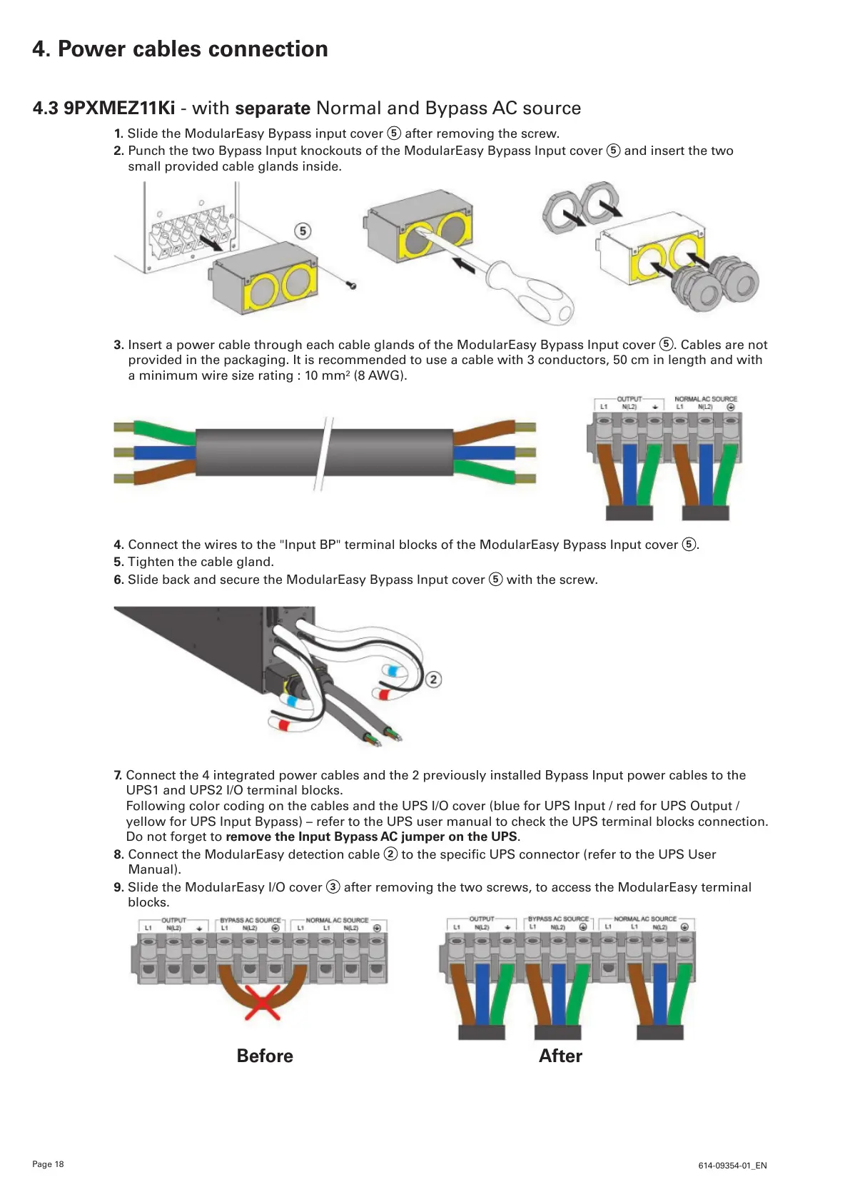
4.3 9PXMEZ11Ki - with separate Normal and Bypass AC source
1. Slide the ModularEasy Bypass input cover
5
after removing the screw.
2. Punch the two Bypass Input knockouts of the ModularEasy Bypass Input cover
5
and insert the two
small provided cable glands inside.
3. Insert a power cable through each cable glands of the ModularEasy Bypass Input cover
5
. Cables are not
provided in the packaging. It is recommended to use a cable with 3 conductors, 50 cm in length and with
a minimum wire size rating : 10 mm² (8 AWG).
4. Connect the wires to the "Input BP" terminal blocks of the ModularEasy Bypass Input cover
5
.
5. Tighten the cable gland.
6. Slide back and secure the ModularEasy Bypass Input cover
5
with the screw.
7. Connect the 4 integrated power cables and the 2 previously installed Bypass Input power cables to the
UPS1 and UPS2 I/O terminal blocks.
Following color coding on the cables and the UPS I/O cover (blue for UPS Input / red for UPS Output /
yellow for UPS Input Bypass) – refer to the UPS user manual to check the UPS terminal blocks connection.
Do not forget to remove the Input Bypass AC jumper on the UPS.
8. Connect the ModularEasy detection cable
2
tothespecicUPSconnector(refertotheUPSUser
Manual).
9. Slide the ModularEasy I/O cover
3
after removing the two screws, to access the ModularEasy terminal
blocks.
4. Power cables connection
Before After
 Loading...