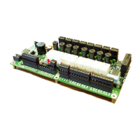
Redundant Power Supply Sequencer Module (RPSSM)
Appendix P – Redundant Power Supply Sequencer
Module (RPSSM)
The Redundant Power Supply Sequencer Module (RPSSM) provides
your ControlWave with dual power supplies for operational redundancy.
You can use the RPSSM in place of the standard power supply sequencer
module (PSSM) in the following ControlWave models:
ControlWave Process Automation Controller
ControlWave I/O Expansion Rack
ControlWave Redundant Controller
The RPSSM includes two independent power supplies: a primary power
supply and a backup power supply. Should the primary power supply fail,
operations automatically continue using the backup supply, and you can
“hot-swap” the failed power supply with a spare unit without interrupting
control operations. The RPSSM also supports hot swapping of I/O
modules. However, you cannot replace the RPSSM itself without first
turning off power to the ControlWave.
When used as part of a redundant system, the failure of one of the two
power supplies in a redundant power supply sequencer module would not
force a failover to the other controller. Only the loss of both power
supplies on the redundant power supply sequencer module would trigger
a failover.
Caution
There is a slight difference between the two redundant power supplies.
One uses a black anodize bracket, the other a gold irridite bracket.
Should a power supply fail, you must use a replacement supply that has
an identical bracket assembly (black anodize or gold irridite). The RPSSM
must have one power supply with each type of assembly or it will not
function. You cannot have two black anodize power supplies installed or
two gold irridite supplies installed on the same RPSSM.
Installing the RPSSM
To ensure safe use of this product, please review and follow the
instructions in the following supplemental documentation:
Supplement Guide - ControlWave Site Considerations for Equipment
Installation, Grounding, and Wiring (S1400CW)
ESDS Manual – Care and Handling of PC Boards and ESD Sensitive
Components (S14006)
If needed, first adjust jumpers as described in Setting Jumpers.
Slide the RPSSM into slot 1 (see Figure P-1) prior to installing the CPU
module. You can wire power and watchdog connections at this time.
However, for safety reasons and to prevent accidental damage to your
bulk DC power supply, we recommend you do not connect pluggable
Revised Nov-2010 Installation and Use P-1
 Loading...

