Redundant Power Supply Sequencer Module (RPSSM)
terminal block connectors TB1, TB2, and TB3 to the RPSSM until you
have installed, wired, and configured the CPU module.
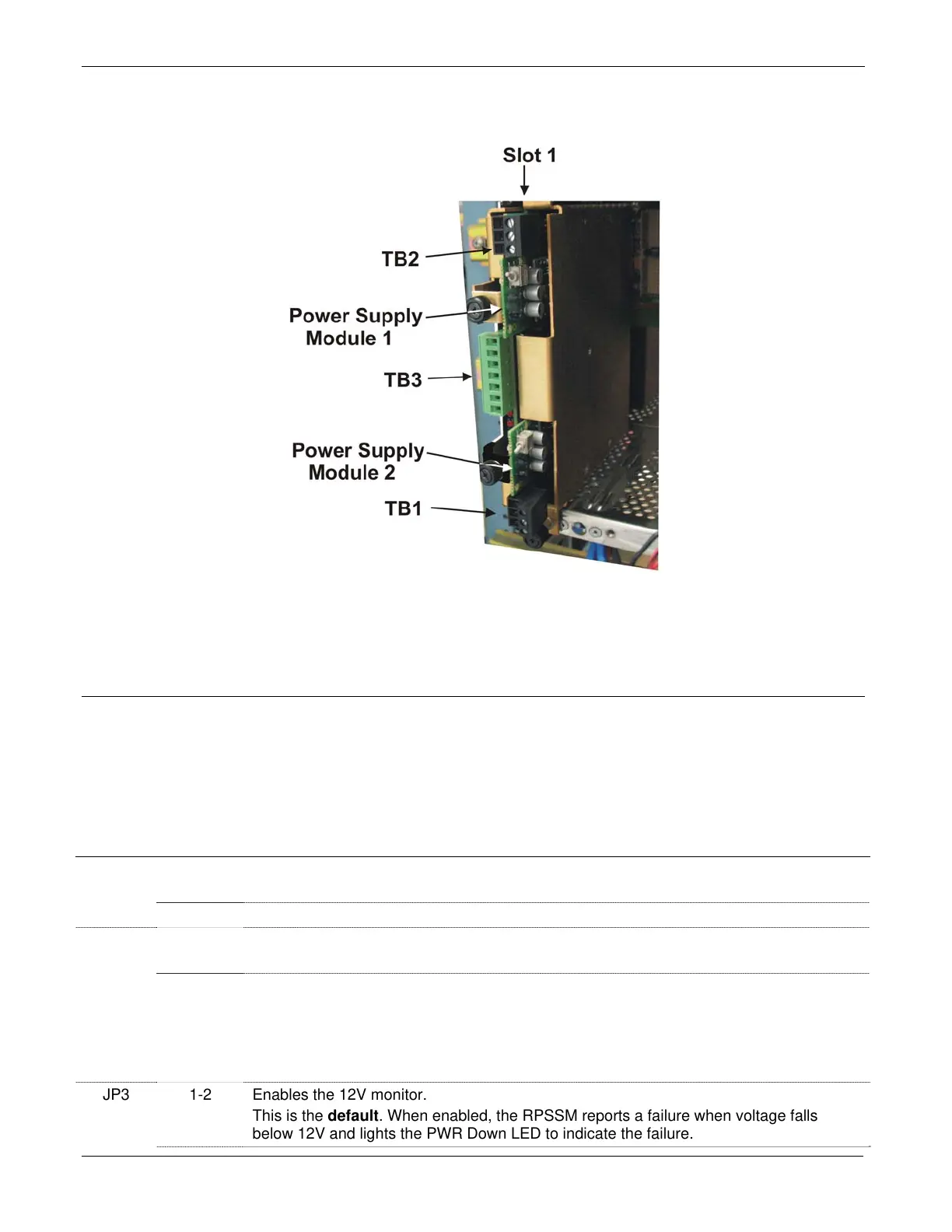
Figure P-1. RPSSM Installed in ControlWave Slot #1 of a ControlWave Redundant Controller
Setting Jumpers
Depending upon how you are using the RPSSM, you may have to change
one or more jumpers from their factor default positions. See Table P-1 for
a list of the jumpers and their functions; see Figure P-3 for jumper
locations.
Table P-1. RPSSM Jumpers
Jumper Position Description
JP1 1-2 Enables the watchdog circuitry.
This is the default. Watchdog wiring is discussed later in this document.
2-3 Disables the watchdog circuitry.
JP2 1-2 Sets the RPSSM as always the on-line unit.
This is the default. Use this setting if the RPSSM is not installed in a redundant system.
2-3 Specifies that the RPSSM is part of a redundant system.
Choose this position if the RPSSM is installed:
In a ControlWave Redundant Controller or
In a ControlWave Controller that is part of a redundant pair or
In a ControlWave I/O Expansion Rack that is part of a redundant pair.
JP3 1-2 Enables the 12V monitor.
This is the default. When enabled, the RPSSM reports a failure when voltage falls
below 12V and lights the PWR Down LED to indicate the failure.
P-2 Installation and Use Revised Nov-2010

 Loading...


