ControlWave Instruction Manual (CI-ControlWave)
Table 3-15. Jumper Assignments: Non-isolated HSC Module
Jumper Purpose Description
W1 Enables/disables LEDs on
module
Pins 1-2 installed = Enable LEDs (Factory default).
Pins 2-3 installed = Disable LEDs
Wiring the Module
Figure 3-31 shows field wiring assignments for locally terminated
isolated RTD modules. Figure 3-32 shows field wiring assignments for
rem
otely terminated isolated RTD modules.
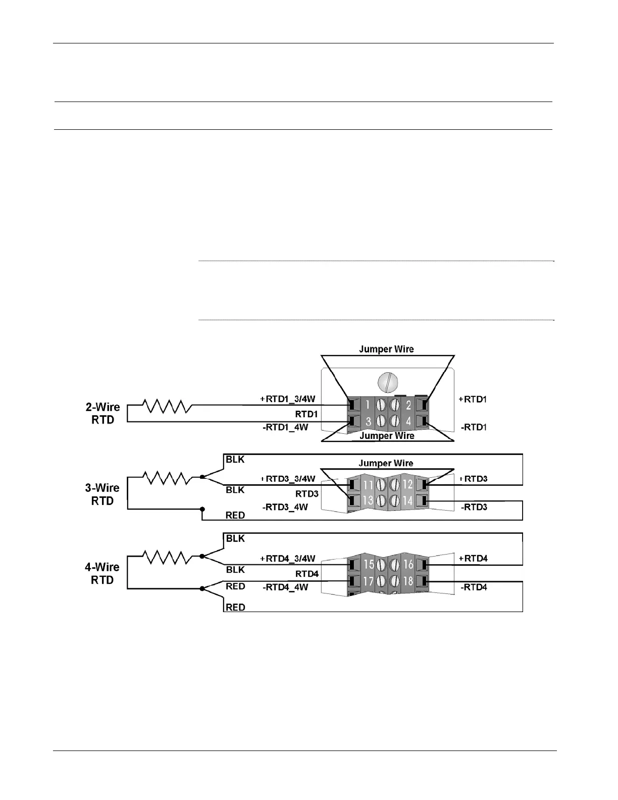
Figure 3-30 provides wiring diagrams for 2-wire, 3-wire, and 4-wire
RTDs to the local RTD m
odule terminal blocks; wiring assignments,
such as +RTD#_3/4W, -RTD#_4W, +RTD# and –RTD# are similar to
those assigned to the Remote DIN-rail mountable terminal blocks.
Note: To maintain specified accuracy with a 3-wire RTD, you must
match the two field wires that source and sink the RTD current
within 0.01 ohms (matched in length and matched in wire type)
and the ambient temperature on these wires must be the same.
Figure 3-30. Isolated RTD Module - 2-Wire, 3-Wire & 4-Wire Wiring Diagram
3-36 I/O Modules Revised Nov-2010

 Loading...


