FloBoss 103/104 Instruction Manual
2-10 Installation and Use Revised August-2017
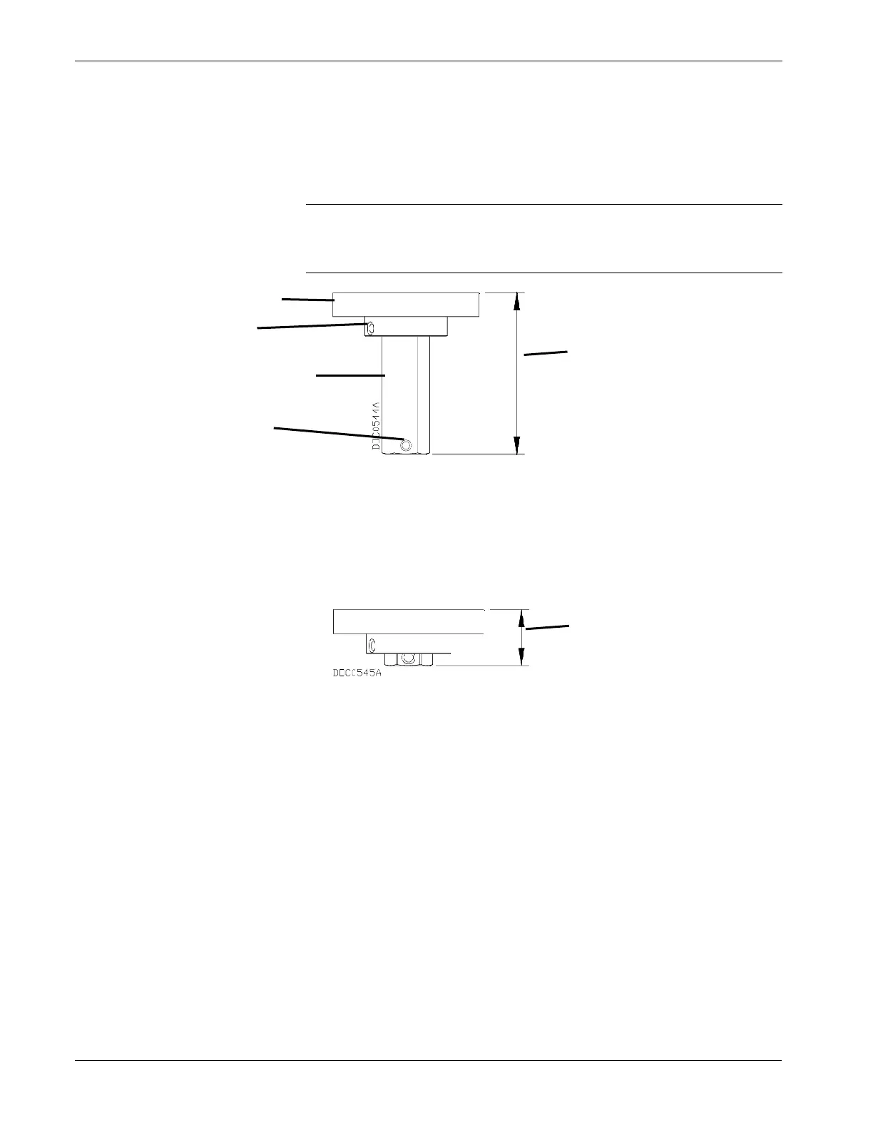
5. Thread the magnet assembly on to the shaft adaptor until the top of
the magnet is between 0.68–0.71 inches above the meter housing
(refer to Figure 2-6). The magnet set-screw should be positioned
over a flat in the hex shaft adaptor. Tighten the set-screw to lock the
magnet assembly in place. Refer to Figure 2-7 and Figure 2-8.
Note: Align the magnet assembly so that the magnet set-screw
contacts one of the shaft adaptor flats and not the shaft
adaptor set-screw or any threaded areas.
1.90 in. Max – 1.70 in. Min
Figure 2-7. Magnet Installed on Long Shaft Adaptor
0.66 in. Max – 0.46 in. Min
Figure 2-8. Magnet Installed on Short Shaft Adaptor
6. Insert 0.25 inch diameter dowel pins (user-supplied) in two of the
5/16-18 UNC threaded holes on the top of the rotary meter. These
pins should extend at least 1.25 inches above the meter housing so
that they can be easily removed later.
7. Place the gasket provided over the dowel pins and rest it flatly on
the meter housing.
8. Position the FB104 over the meter housing and carefully lower it
into place using the dowel pins to guide alignment.
9. Loosely install two 5/16-18 x 7/8 long cap screws with lock washers
(user-supplied) into the two threaded meter holes which do not have
dowel pins. 18-8 stainless steel fasteners and washers are
recommended.
1
.
9
0
i
n
.
M
a
x
.
–
1
.
7
0
i
n
.
M
i
n
.

 Loading...


