FloBoss 103/104 Instruction Manual
Revised August-2017 Input/Output 4-7
▪ Toggle mode.
▪ Latched mode.
▪ Timed discrete output (TDO) mode.
Note: The switch for the selectable Analog Output/Discrete Output
(DO-1) should be in the DO position, when configured for use as
a Discrete Output.
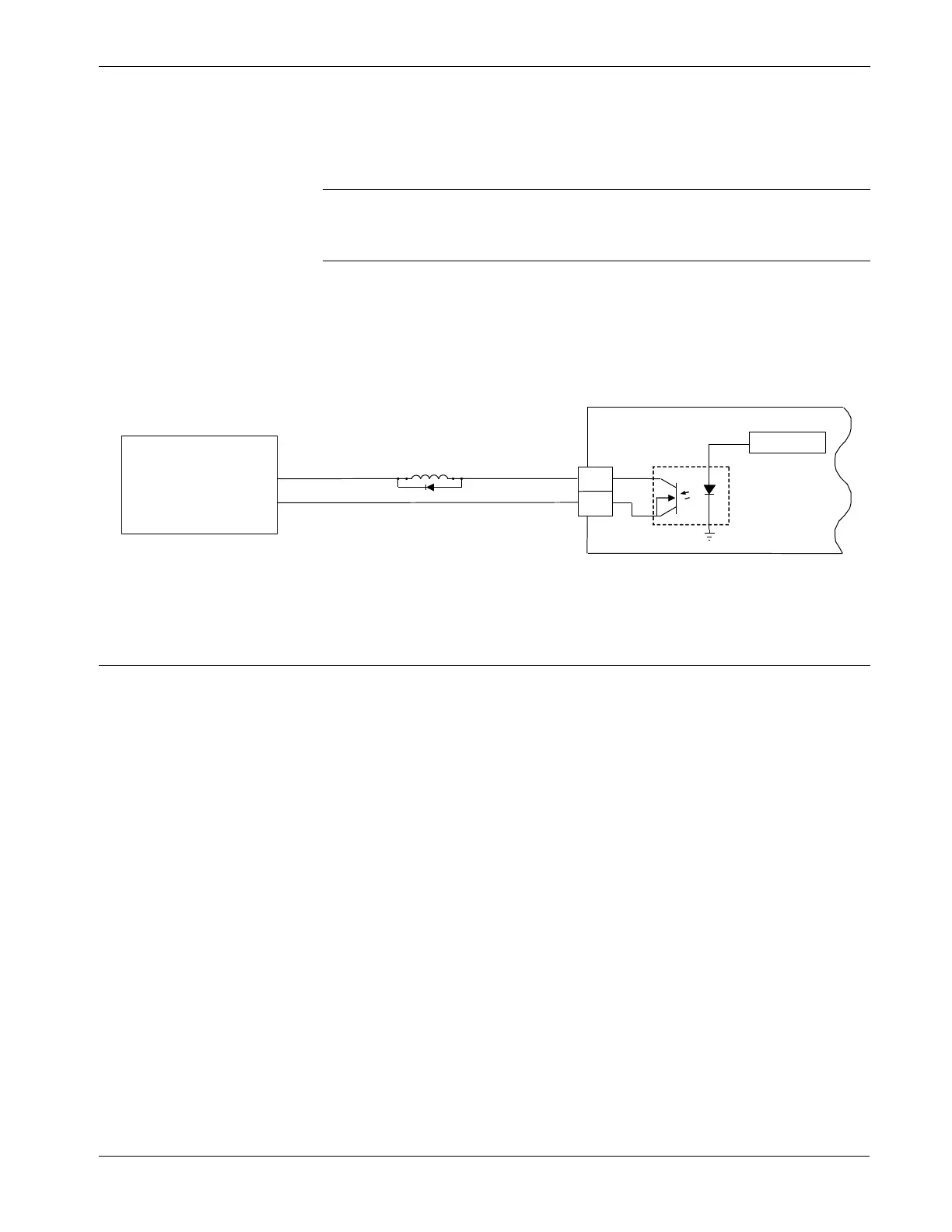
4.6.1 Wiring the Discrete Output
Figure 4-7 shows the DO wiring. The “+” terminal is the normally open
contact and the “–” terminal is the common.
Figure 4-7. Solid State Relays – Discrete Outputs
4.7 Pulse Input
The Pulse Input (PI) counts pulses from pulse-generating devices. The
FB100 Pulse Input circuits are physically the same as the Discrete
Inputs. The Pulse Input, after the isolation, routes to a pulse
accumulator, where the pulses are counted and accumulated.
You configure the selectable Pulse Inputs/Discrete Inputs as pulse
inputs using ROCLINK 800 software. Refer to Section 4.1.1.
4.7.1 Wiring the Pulse Input
Figure 4-8 shows DI wiring. The “+” terminal is a positive source
voltage and the “–” terminal is the signal return. To use the channel as a
pulse input (shown in Figure 4-8), connect the “+” and “–” field wires
to terminals “PI-1+” or “PI-2+” and “–”.

 Loading...


