FloBoss 103/104 Instruction Manual
4-4 Input/Output Revised August-2017
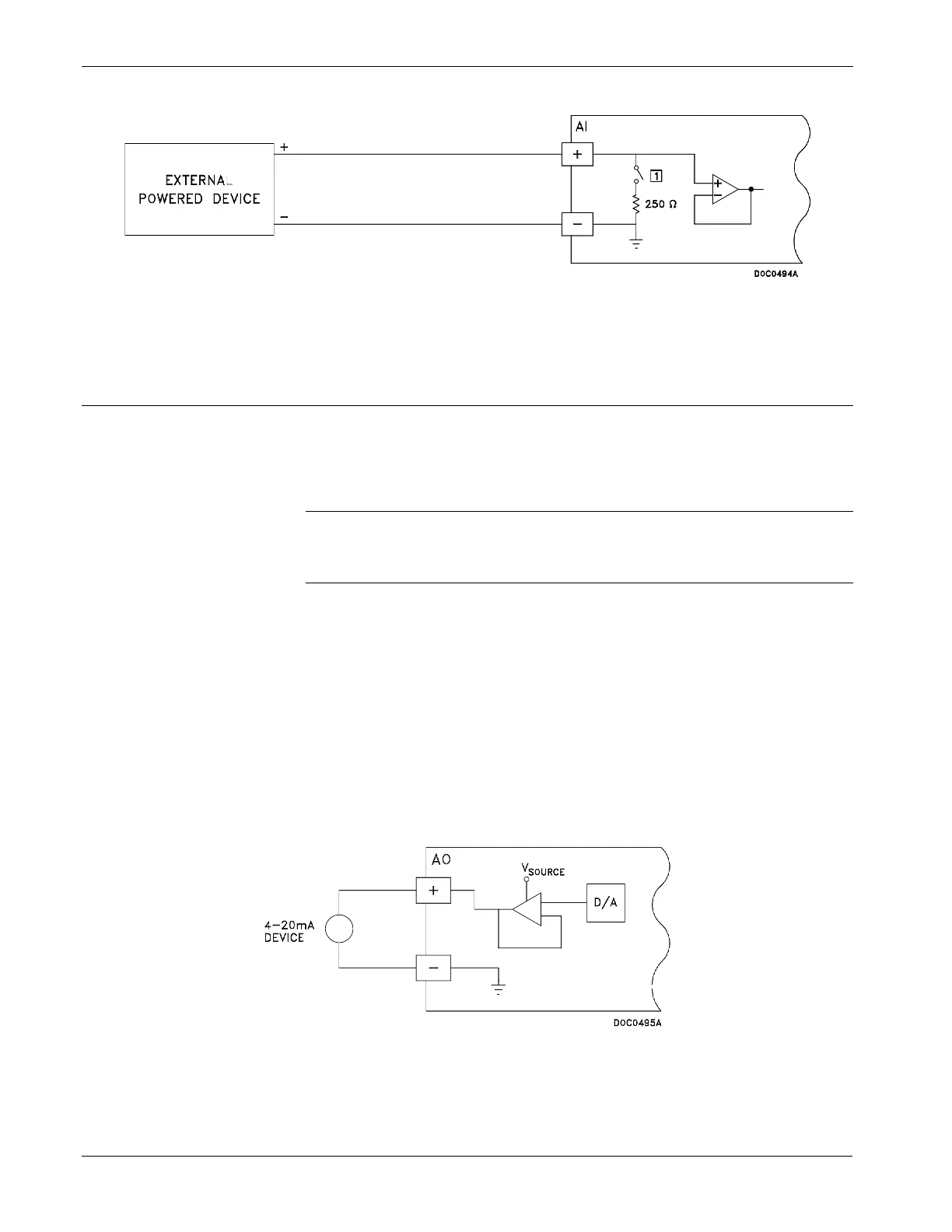
Figure 4-2. Analog Input Wiring
4.4 Analog Output
The Analog Output (AO) on the 6-point I/O termination board provides
a 4–20 mA current source. The analog outputs use a 12-bit D/A
converter with A/D values of 0 and 4095.
Note: The switch for the selectable Analog Output/Discrete Output
should be in the AO position, when configured for use as an
Analog Output.
The Analog Output (AO) on the older 4-point I/O termination board
provides either a 1–5 volt signal or a 4–20 mA current control. The
analog outputs use an 8-bit D/A converter with A/D values of 0 and
250. The AO is located at Point Number B2.
4.4.1 Wiring the Analog Output (6-point I/O Board)
Figure 4-3 shows wiring for the Analog Output, where:
AO+ Positive
AO- Common
Figure 4-3. Analog Output Wiring for 6-point I/O Board

 Loading...


