FloBoss 103/104 Instruction Manual
4-6 Input/Output Revised August-2017
Note: The selectable analog inputs/discrete input channels should have
the 250-ohm resistor disabled when configured for use as
discrete inputs.
4.5.1 Wiring the Discrete Input
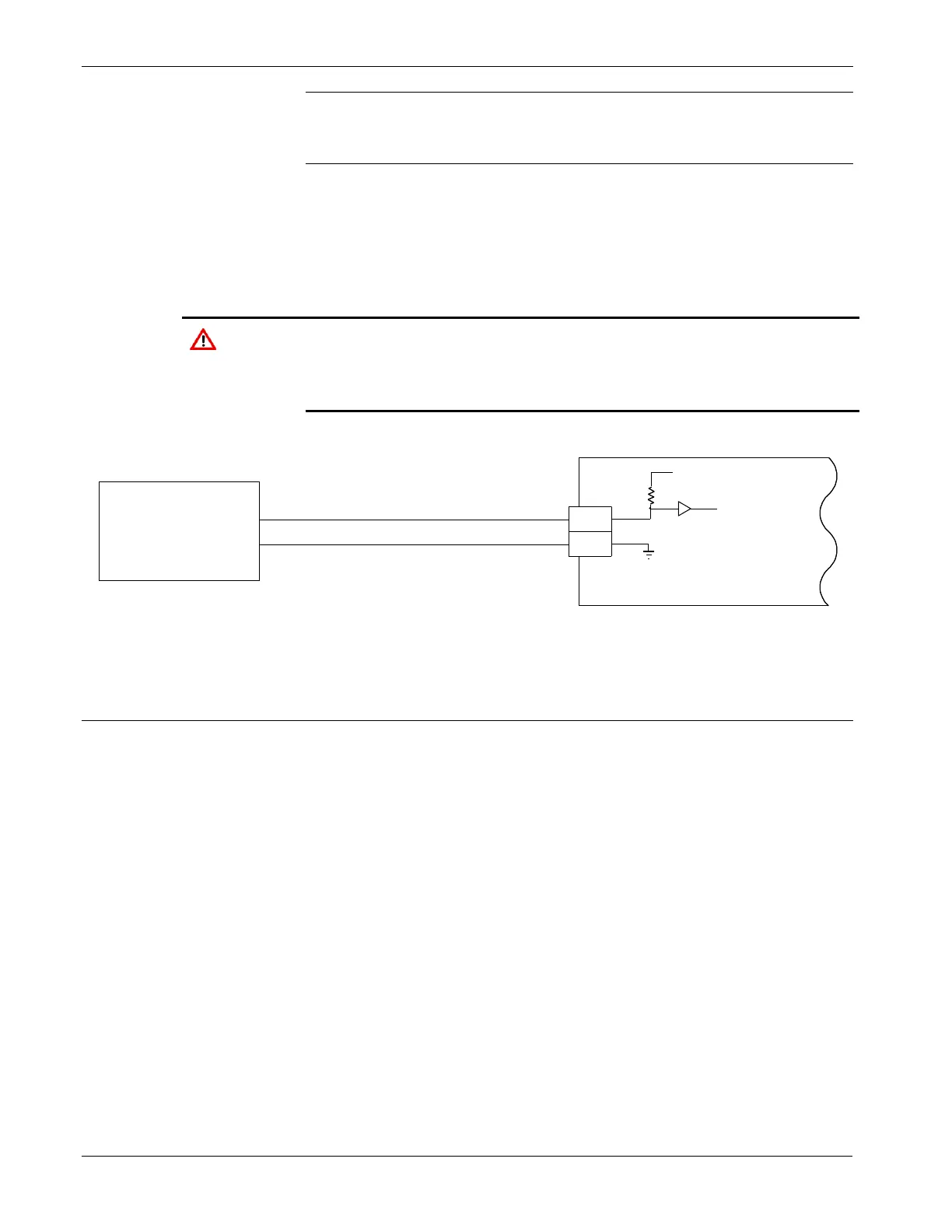
Figure 4-6 shows the terminals for connecting the DI wiring. The “+”
terminal is the positive signal input and the “–” terminal is the signal
common. The Discrete Input operates by providing a closed contact
across terminals “+” and “-”. Refer to Figure 4-6.
The Discrete Input is designed to operate only with non-powered
discrete devices, such as “dry” relay contacts, open collector devices,
or isolated solid state switches. Use of the DI channel with powered
devices may cause improper operation or damage.
Figure 4-6. Discrete Input Wiring
4.6 Discrete Output
The Discrete Output (DO) provides a solid-state switch to control relays
and to power small electrical loads. The DO circuitry is optically
coupled to help isolate the processor board from the input signal.
DO functions include:
▪ Sustained discrete outputs.
▪ Momentary discrete outputs.
▪ Slow pulse-train outputs.
The Discrete Output channel is a normally-open, FET switch. The
Discrete Output is a solid-state switch enabled by individual signals
from the processor I/O lines and capable of handling 50 V dc at 0.2 A
maximum.
The Discrete Output on the I/O termination board can be used in:

 Loading...


