FloBoss 103/104 Instruction Manual
7-2 Pulse Interface Module Revised August-2017
• Static pressure is sampled once per second.
• Temperature is sampled and linearized once per second.
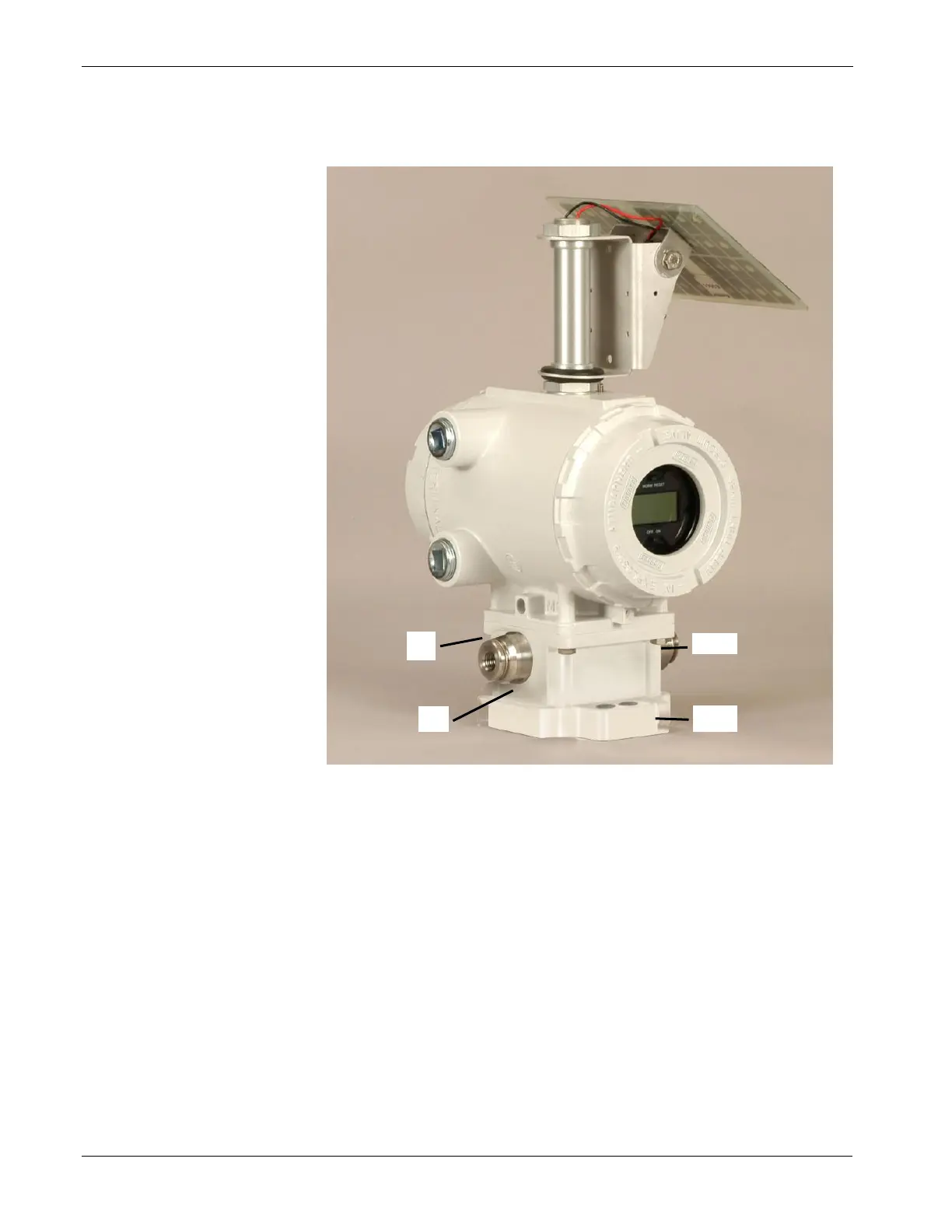
Figure 7-1. FloBoss 104 Assembly
The FB104 implements standard PI and AI alarming along with sensor
and flow alarms. If the sensor fails to communicate (either during
initialization or run time), the Failure bit in the Pulse Input and Analog
Input alarm code is set. If you enable alarms, the alarm also appears in
the Alarm Log.
The two pulse inputs in the Pulse Interface Module count pulses
acquired from a rotary meter. PI1 is for clockwise (CW) rotation; PI2 is
for counter-clockwise (CCW) rotation. You can use the optional pulse
inputs on the termination board for other pulse input devices.

 Loading...


