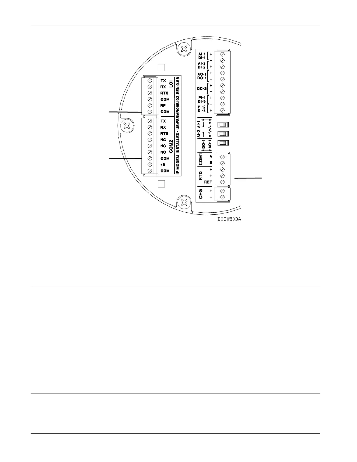
Figure 5-1. Communication Port Locations on Termination Board
5.2 EIA-485 (RS-485) Communications Wiring
The EIA-485 communication accommodates RS-485 and EIA-485
signals on the Comm 1 port located on the termination board.
Wiring should be twisted-pair cable. The terminals and their functions
are Pin 1 is Terminal B and Pin 2 is Terminal A. Refer to Figure 5-1.
Connect A on the FB100 to A or +, and connect B on the FB100 to B or
-. Should you encounter difficulties establishing a connection, try
reversing the connections. Note that for RS-485 installations the TX
terminal (as labeled) is the A connection and the RX terminal is the B
connection.
5.3 Local Operator Interface Port Wiring
The Local Operator Interface (LOI) port provides connections for a
built-in EIA-232 (RS-232) communications interface to a local
configuration and monitoring device, typically a PC running a Microsoft

 Loading...


