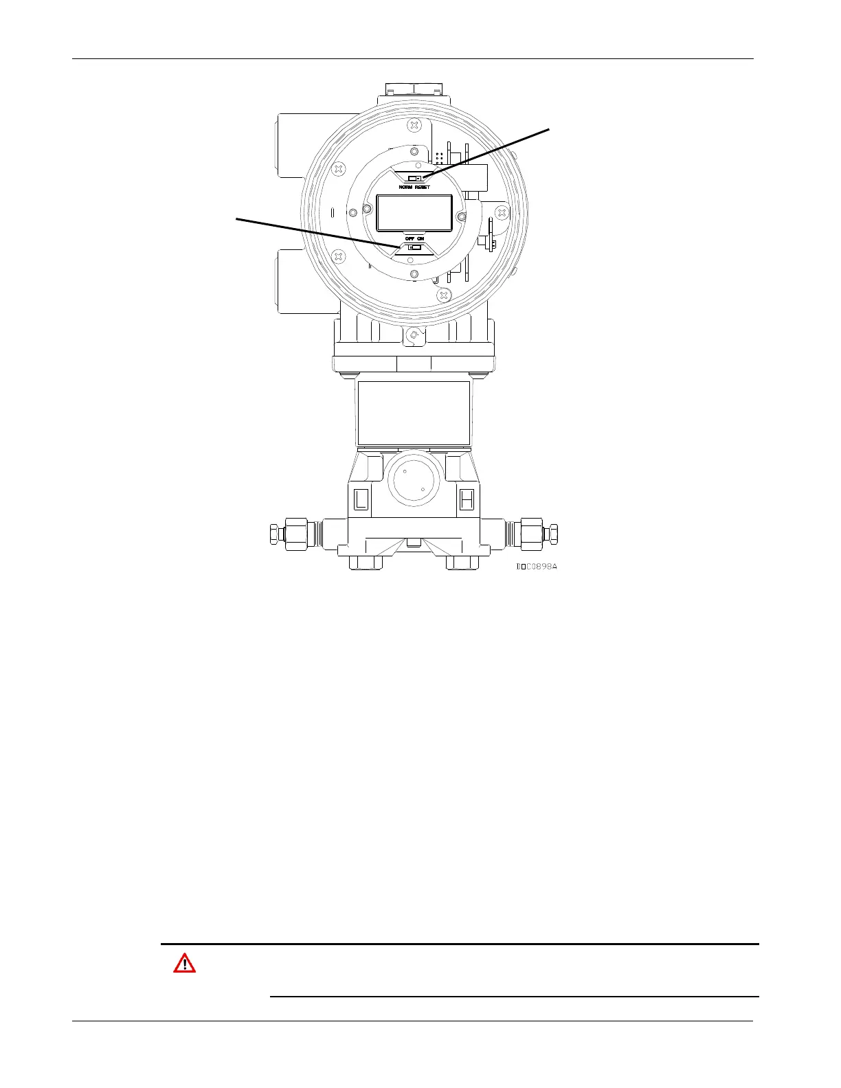
Figure 2-9. On/Off Power Jumper (FB103 with Optional LCD)
3. Reattach the top-end cap cover (LCD end). Screw the cover on until
metal contacts metal. Do not over-tighten the cover.
After the FB100 start-up diagnostics (RAM and other internal checks)
complete, the optional LCD displays the date and time to indicate that
the FB100 has completed a valid reset sequence. If the LCD does not
come on, refer to Chapter 9 for possible causes and resolutions.
2.4.2 Operation
Once startup is successful, you must configure the FB100 to meet the
requirements of the application. ROCLINK 800 Software User Manual
(part D301159X012) details the procedure for configuring the FloBoss
and calibrating the I/O. Once you configure and calibrate the FB100-
Series. You can place it into operation.
When the enclosure end caps are unscrewed, local configuration or
monitoring of the FB100-Series through its LOI port must be performed
only in an area known to be non-hazardous. Performing these

 Loading...


