ER5000 —
69
Getting Started
7
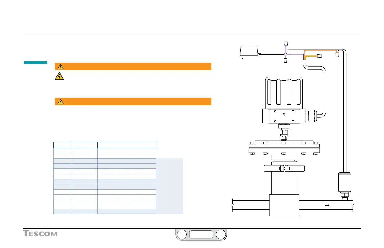
Connect the transducer wiring to provide a
feedback signal
WARNING
The controller must be disconnected from the power supply before
any additional wiring or change to jumper configuration is
performed. Do not reconnect the power supply until all additional
wiring connections have been made and are properly installed.
WARNING
Installation in a hazardous location requires additional steps not
described in this section. Refer to Installing a Hazardous Location
Model (ER5050) on page 110 for more information.
1. Refer to Table 3 below to verify correct wiring.
Table 3: Main Cable Wiring for Power Supply
J3 Pins Wire Color Function
1 brown +setpoint input
2 red -setpoint input
3 orange +feedback input
4 yellow -feedback input
5 green -RS485 network connection
6 blue +RS485 network connection
7 violet +24V DC power
Standard
Installation
8 gray 24V return (power ground)
9 white +5V output (5 mA max.)
10 black analog signal/board ground
*11 *pink analog signal output
(active in Enhanced “F” models ONLY)
12 tan analog signal/board ground
(continued next page)
Transducer
Power
Supply
+24V DC
VIOLET
YELLOW
ORANGE
+ SUPPLY
+ SUPPLY
+ OUTPUT
GRAY
TAN
Supply Pressure
To Process
Regulator
GROUND
Adaptor
Figure 12: Connect the ER5000 to External Transducer
 Loading...


