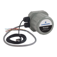
ER5000 —
70
Getting Started
Connect the transducer wiring to provide a
feedback signal (cont.)
2. Connect the orange feedback input wire (Pin 3) to the
signal output of the transducer, which is Pin 2 or B on
TESCOM™ transducers.
3. Connect the positive wire from the 24V DC power supply
to the power input of the transducer, which is Pin 1 or A on
TESCOM transducers.
4. Connect the yellow feedback return wire (Pin 4) to the tan
analog ground wire (Pin 12).
NOTENOTE
CAUTIONCAUTION
WARNINGWARNING
This is necessary to complete the ground circuit for the
signal from the transducer.
For other applications and wiring congurations, refer to the
Installation Variations section.

 Loading...


