25
3.3 ELECTRICAL INPUT CONNECTIONS
In order to provide a safe and convenient means to completely remove all electrical power from the machine, it is highly
recommended that a line disconnect switch be installed in the input circuit of the machine.
3.3.1 INPUT ELECTRICAL REQUIREMENTS
The primary input voltage requirements are shown on the power source nameplate. The power source is designed to be
operated from 208/230 vac single phase 50/60 Hz.
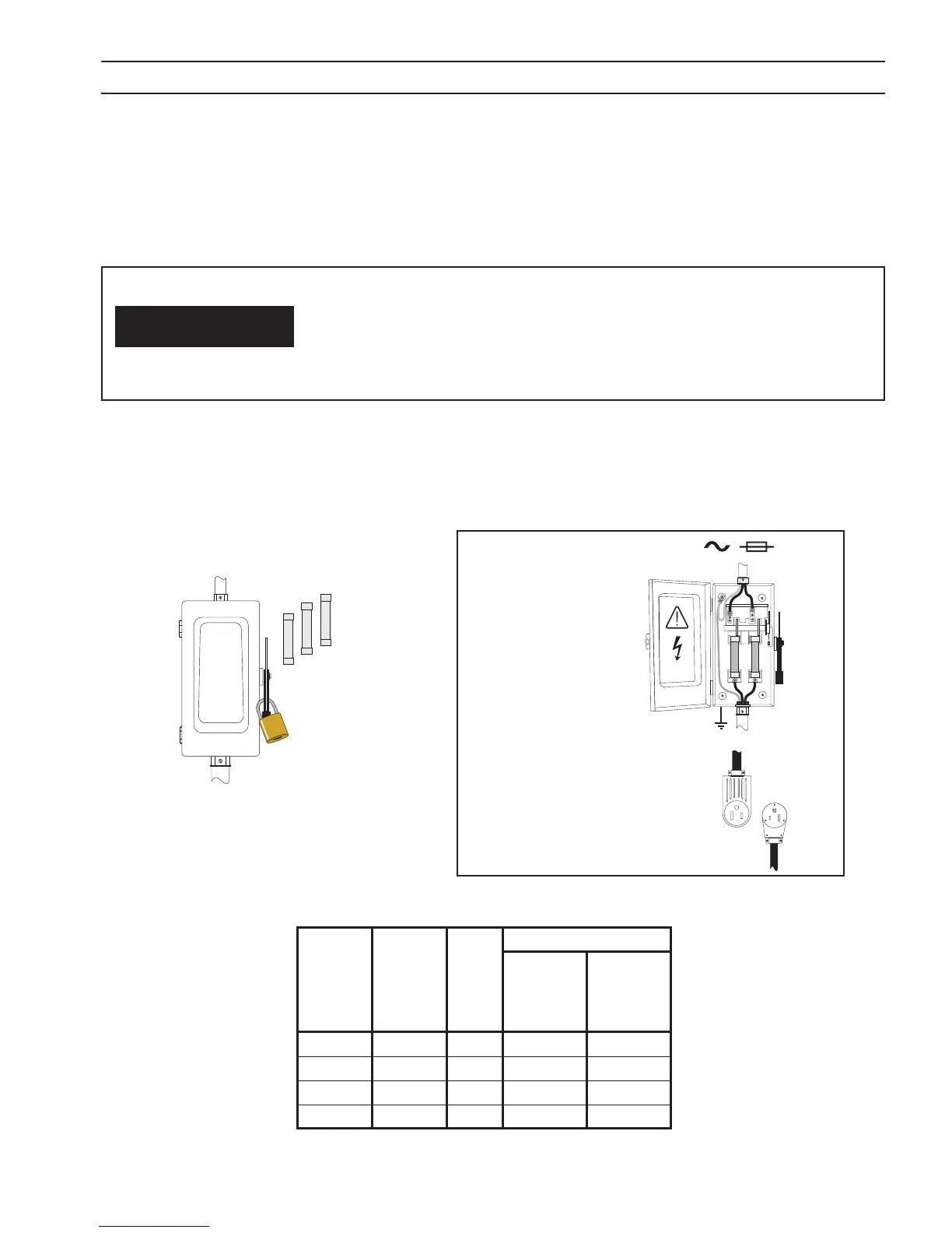
Before making electrical input connections to the welding machine, “Machinery
Lockout Procedures” should be employed. If the connections are to be made from
a line disconnect switch, the switch should be padlocked in the o position. If the
connection is to be made from a fusebox, remove the fuses and padlock the cover
closed. If no locking facilities are available, attach a red tag to warn others not to
energize the circuit.
Typical Installation - User
Supplied Power Discon-
nect Box, Receptacle and
Plug
SECTION 3 INSTALLATION
WARNING
Primary
Input
Volts
Full
Load
Line
Amperes
Fuse
Size
Recommended
Primary
Input
Conductor
Size
Ground
Conductor
Size
208 57 90 8 8
230 52 90 8 8
460 26 30 12 12
575 20 30 12 12
Input Conductor and Fuse Size
 Loading...