35
SECTION 4 OPERATION
4.0 OPERATION
4.1 STANDARD CONTROLS
4.1.1 POWER ON/OFF SWITCH & LAMP
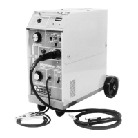
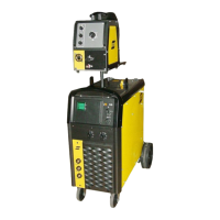
The main power switch is located on the front panel in the upper left-hand corner. This switch energizes the main trans-
former, control circuitry and illuminates the Power “ON” lamp. (Figures 12 &13)
4.1.2 FAULT LAMP (Figure 12)
The fault lamp is congured for future use and is not currently activated.
4.1.3 TEMP LAMP (Figure 12)
The TEMP lamp illuminates if an over temperature condition occurs within the Multimaster 260. This condition may be caused
by excessive duty cycle or over-current conditions. When an over temperature condition occurs, the welding output is turned
o and the unit must be allowed to cool. The machine will automatically reset when the temperature falls to a safe level.
4.1.4 PROCESS SELECTOR SWITCH (Figure 12)
The three position process selector switch is located in the upper righthand corner of the control panel. The process selector
switch provides the visual indication of which process (Mig, Tig or stick) has been selected.
4.1.5 SECONDARY WELDING CONNECTIONS
The secondary output welding terminals, POS (+) and NEG (-) are located in the lower right of the front panel, directly beneath
the Euro Connector (Figure 13). See 4.4, 4.5, and 4.6 for Setup Guides for specic application.
4.1.6 DIGITAL DISPLAYS (WFS, AMPS & VOLTS)
The digital displays located on the left side of the control panel are multi-functional depending on the welding process
being used.
4.1.7 MIG WELDING
In the Mig process mode, the digital displays will read preset wire feed speed in inches per minute and preset arc volts when
the PRESET button is pressed. Once welding begins, the displays will show average welding current and volts in the top and
bottom display, respectively. The displays have a “HOLD” circuit that retains the welding conditions. After welding stops, the
display will continue to show the last welding current and voltage sampled for 10 seconds, then returns to “0”.
WARNING
Comply with all ventilation, re and other safety requirements for arc welding as
established in the SAFETY Section at the front of this manual.

 Loading...