45
4.6 STICK WELDING SET-UP
When the PROCESS switch is placed in the STICK position, the Multimaster 260 turns “ON” the weld contactor so that power
is immediately available to the output connection. This means that the STICK electrode holder is “HOT”, and an arc will strike
when the electrode comes in contact with the workpiece or any other object at ground potential.
Step 1. Choose the weld parameters based on the Stick Electrode and diameter being used from Table 5 - STICK PARAM-
ETERS CHART.
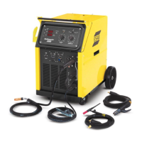
Step 2. Be sure to set the polarity to DCEP (Electrode Positive) by placing the Electrode Holder cable in the Positive con-
nection terminal on the front of the power source.
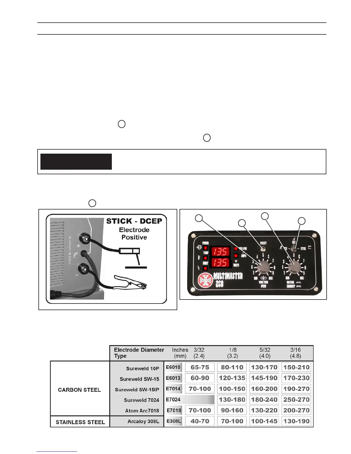
Step 3. Place the WELD PROCESS 1 switch in the STICK (right) position.
Step 4. While holding the PRESET button, turn the VOLTAGE/CURRENT 4 knob to the desired weld current in the top digital
display window.
Step 5. Strike the electrode and start welding. Trim the welding current as needed for the desired puddle control.
When the WELD PROCESS switch is moved to the TIG or STICK position, electrode
becomes electrically “HOT”. Do not allow the electrode to contact ground potential
until you are ready to make a weld.
CAUTION
SECTION 4 OPERATION
Figure 22 - STICK Polarity Connection
4
1
NOTE: Due to built in “Arc Force” control the “Actual” current while weld-
ing may dier from the “Pre-set” value. If the welding voltage falls
below 23 volts, the actual welding current will be greater than the
preset value.
Figure 23 - STICK Front Control Panel
NOTE: The Wirespeed 3 knob has no eect in the STICK mode.
2
Table 5 - STICK PARAMETERS CHART
3
 Loading...