41
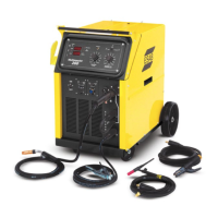
Figure 18 - MIG Polarity Connection
4
2
3
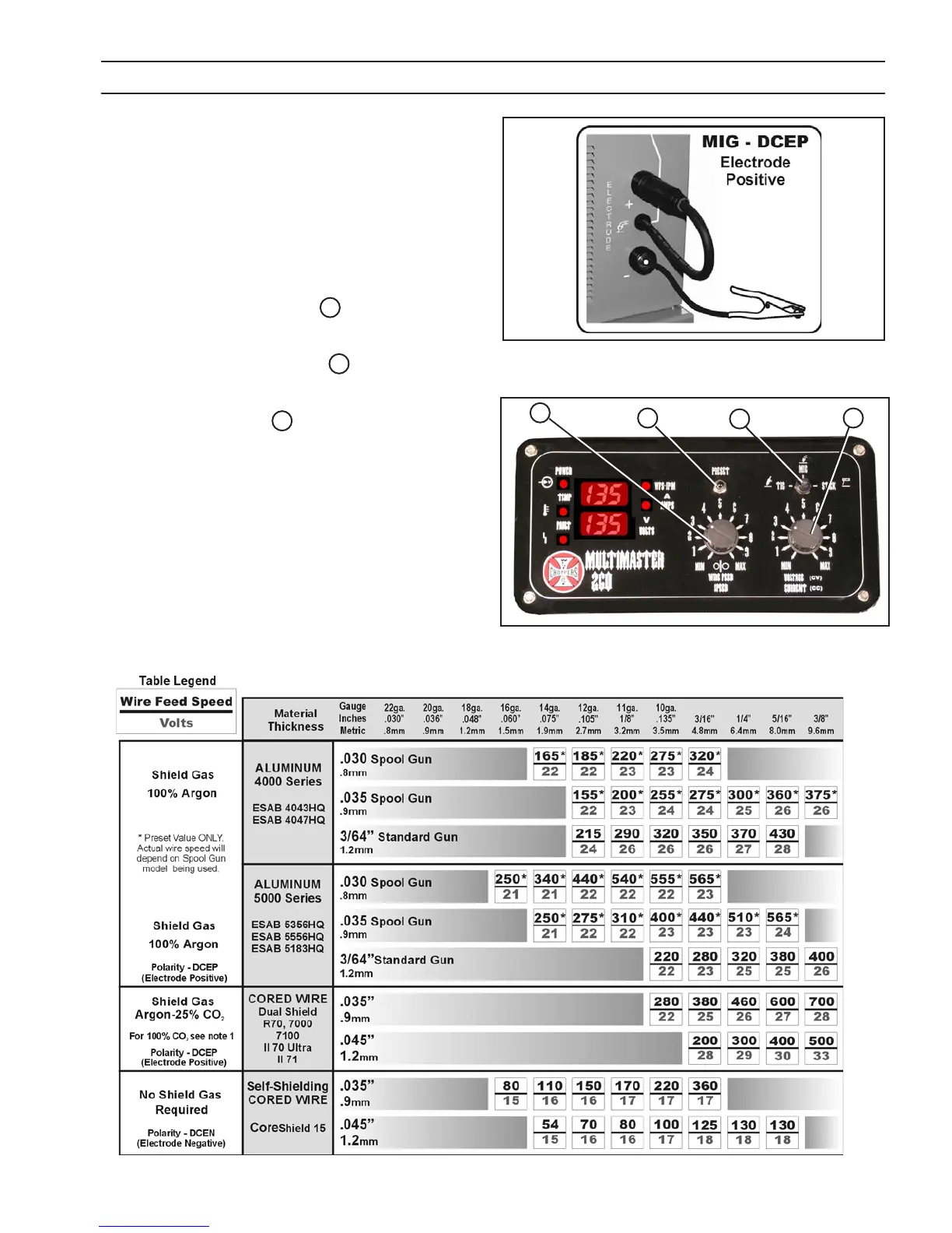
Figure 19 - Mig Front Control Panel
Note 1: When using 100% CO
2
sheilding gas, add 2 volts to the data table value.
Table 3 - MIG PARAMETERS CHART
1
SECTION 4 OPERATION
4.3 MIG WELDING SET-UP
When the PROCESS switch is placed in the MIG position the
Multimaster 260 is set to turn ”ON” when the Mig Gun trigger
is depressed.
Step 1. Choose the weld parameters based of the wire alloy,
diameter, material thickness and shielding gas from
Table 3 - MIG PARAMETERS CHART. Set the polarity
as shown in Table 3 for the process being used.
Step 2. Place the WELD PROCESS 1 switch in the MIG (cen-
ter) position then press the PRESET button.
Step 3. Turn the Wire Speed Knob 3 to the desired speed
in the top digital display window.
Step 4. Turn the VOLTAGE 4 knob to the desired arc voltage
in the bottom digital display window.
Step 5. Set the shielding gas ow rate to 35 cfh by pulling
the gun trigger and turning the adjustment knob on
the R33-FM 580 Flowmeter.
Step 6. Pull the gun trigger and start welding. Trim the wire
speed and volts as needed for the desired arc char-
acteristics.
 Loading...