42
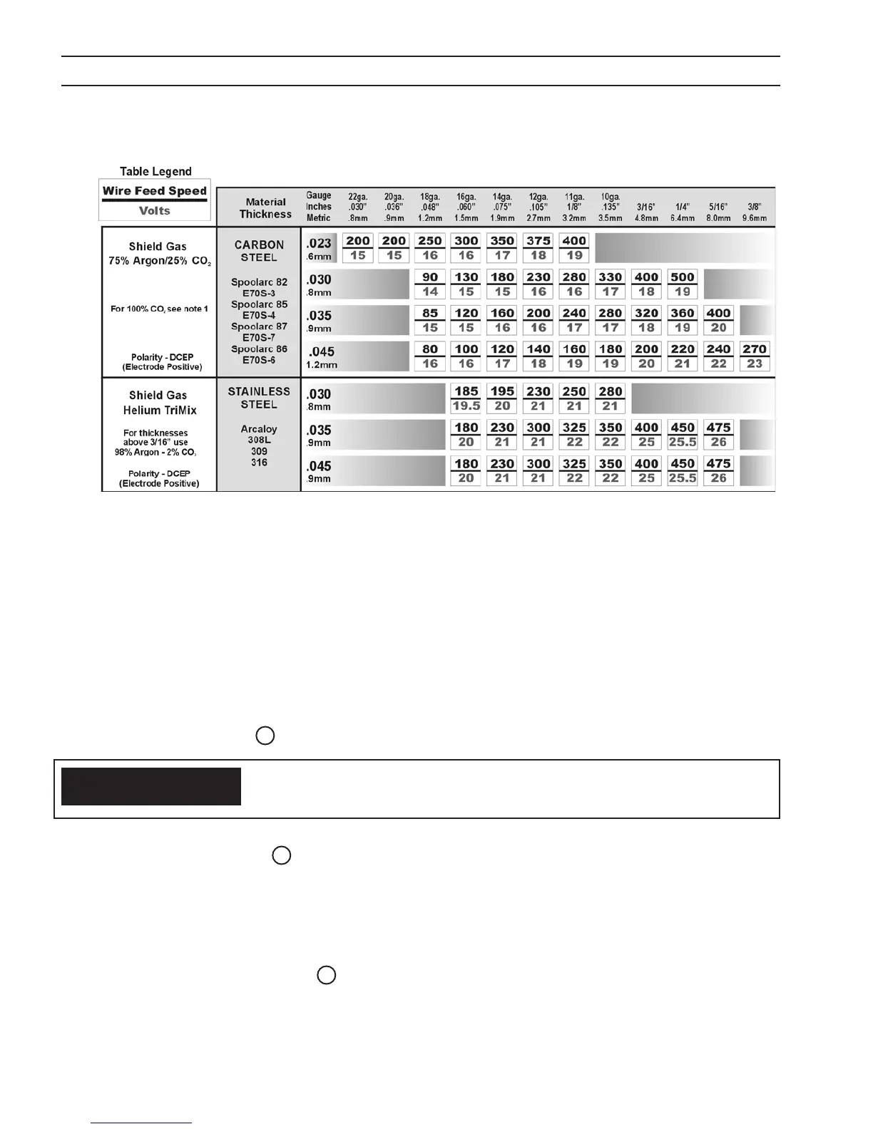
Table 3 - MIG PARAMETERS CHART (Cont’d)
Note 1: When using 100% CO
2
sheilding gas, add 2 volts to the data table value.
SECTION 4 OPERATION
4.4 TIG WELDING SETUP
When the PROCESS switch is placed in the TIG position, the Multimaster 260 turns “ON” the weld contactor so that power
is immediately available to the output connection. The Touch TIG starting system is then enabled.
Step 1. Determine the weld parameters based on the metal thickness in Table 4 or use the ESAB TIG Welding Handbook
(optional) for suggested welding parameters.
Step 2. Be sure to set the polarity to DCEN (Electrode Negative) by placing the Heliarc Torch in the Negative connection
terminal on the front of the power source as shown in Figure 20.
Step 3. Place the WELD PROCESS 1 switch in the TIG (left) position.
Step 4. While holding the PRESET 2 button, turn the VOLTAGE/CURRENT knob to the desired weld current on the top
digital display window.
Step 5. Set the shielding gas ow rate to 20 cfh by opening the manual gas valve on the Heliarc torch and adjusting the
control knob on the R-33-FM-580 owmeter.
Step 6. Touch the tungsten electrode to the workpiece momentarily to establish the welding arc. Trim the current as desired
by turning the VOLTAGE/CURRENT 4 knob.
When the WELD PROCESS switch is moved to the TIG or STICK position, electrode
becomes electrically “HOT”. Do not allow the electrode to contact ground potential
until you are ready to make a weld.
CAUTION
 Loading...