30
3.7.2 WELDING WIRE SPOOL INSTALLATION
Install a spool of welding wire on the spindle as follows:
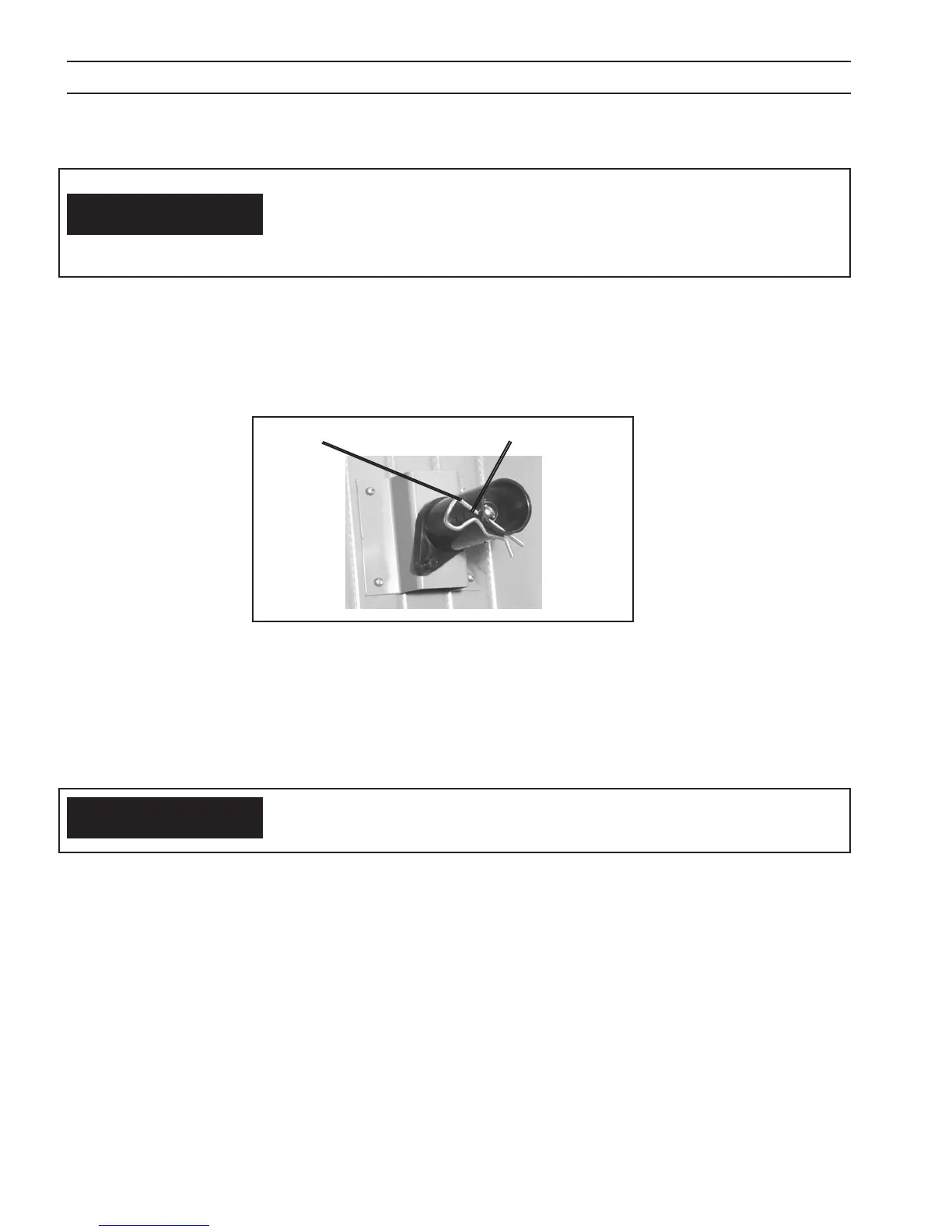
A. Remove the locking pin from the spindle (Figure 8).
B. Place wire spool on the spindle to rotate clockwise as wire is unwound; spindle brake pin must engage hole in spool.
C. Replace the locking pin into the spindle hole closest to the spool.
SECTION 3 INSTALLATION
CAUTION
As with any work area, make sure safety glasses with side shields are worn when
handling or changing wire or clipping wire o at the spool or at the end of the
torch. Hold onto the wire coming o the spool with one hand before clipping.
Serious eye injury can result due to the resilience of the wire which can quickly
unravel, or a cut wire end which may shoot across the room.
Figure 8 - Spindle Assembly
Locking Pin
Spool Spindle
Before threading welding wire, make sure chisel point and burrs have been re-
moved from wire end to prevent wire from jamming in gun or liner.
CAUTION
3.7.3 THREADING WELDING WIRE
A. Turn o power switch.
B. Release pressure drive roll assembly. Check that proper wire diameter grooves are in the inner position.
C. Feed the wire from the spool through the inlet guide, across the drive roll grooves and center guide into the outlet
guide and EURO connection tube.
Make sure that the proper “outlet guide tube” is inserted into the front-panel gun tting for the size and type of wire
being used, see Table for wire feed accessories.
To ensure proper wire feeding, it is important that the wire be kept clean and that the drive rolls be periodi cally
cleaned of any chips or scale that might be carried into the gun liner.
D. Lower pressure roll assembly and secure. Turn the power “on” and feed wire through to gun tip using the gun trigger
to start wire feeding.
 Loading...