26
SECTION 3 INSTALLATION
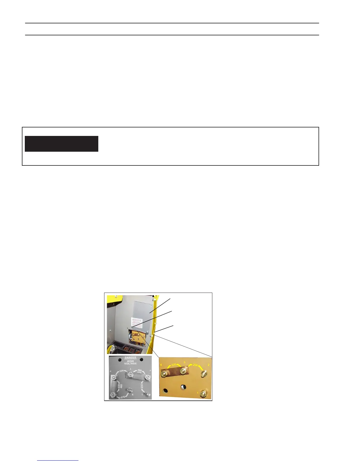
3.4 VOLTAGE CHANGEOVER (Figure 4)
The voltage changeover terminal board is located in the tool compartment on the left side of the machine. As shipped from
the factory, the Multimaster 260 is congured for the highest connectable voltage. If using the other input voltages, the links
on the terminal board (TB) inside the unit must be repositioned for the appropriate input voltage. See gures 4A - 4E for
60Hz input voltage congurations. To gain access to the terminal board, open the access panel on the left side. To change
voltages, perform the following:
A. Remove the left screw ONLY and swing plexiglass door upward.
B. Adjust the copper bar links to the primary voltage being used.
C. Swing clear panel down and secure with screw.
The receptacle should be wired to a separately fused disconnect or circuit breaker by an electrician. This disconnect or
breaker can be wired to a single phase system or two conductors of a three phase system. A third conductor for grounding
must be connected between the disconnect and the receptacle.
3.3.2 INPUT PLUG
The input power cord is provided with an attachment plug. The plug will mate with a 250 volt, 50 Amp receptacle con-
forming to NEMA 6-50R congura tion (208/230 vac model only).
The termi nal labeled GRD is connected to the power source chassis and is for ground
purposes only. This must be connected to a good electrical ground. Do not connect
a conductor from the terminal labeled GRD to any one of the L1, L2 terminals as this
will result in an electrically hot machine chassis.
WARNING
Figure 4 - Voltage Changeover Terminal Board
208/230 Version Shown Installed
Clear Panel Hinges on
corner screw
Remove this
screw only
This screw must
remain in place
Do Not Remove
 Loading...