190-00207-02 GTX 330/330D Installation Manual
Rev. U Page 2-3
2.4 Antenna Installation
2.4.1 Location Considerations
Antenna mounting should utilize the aircraft manufactures Type Certificated antenna location and style of
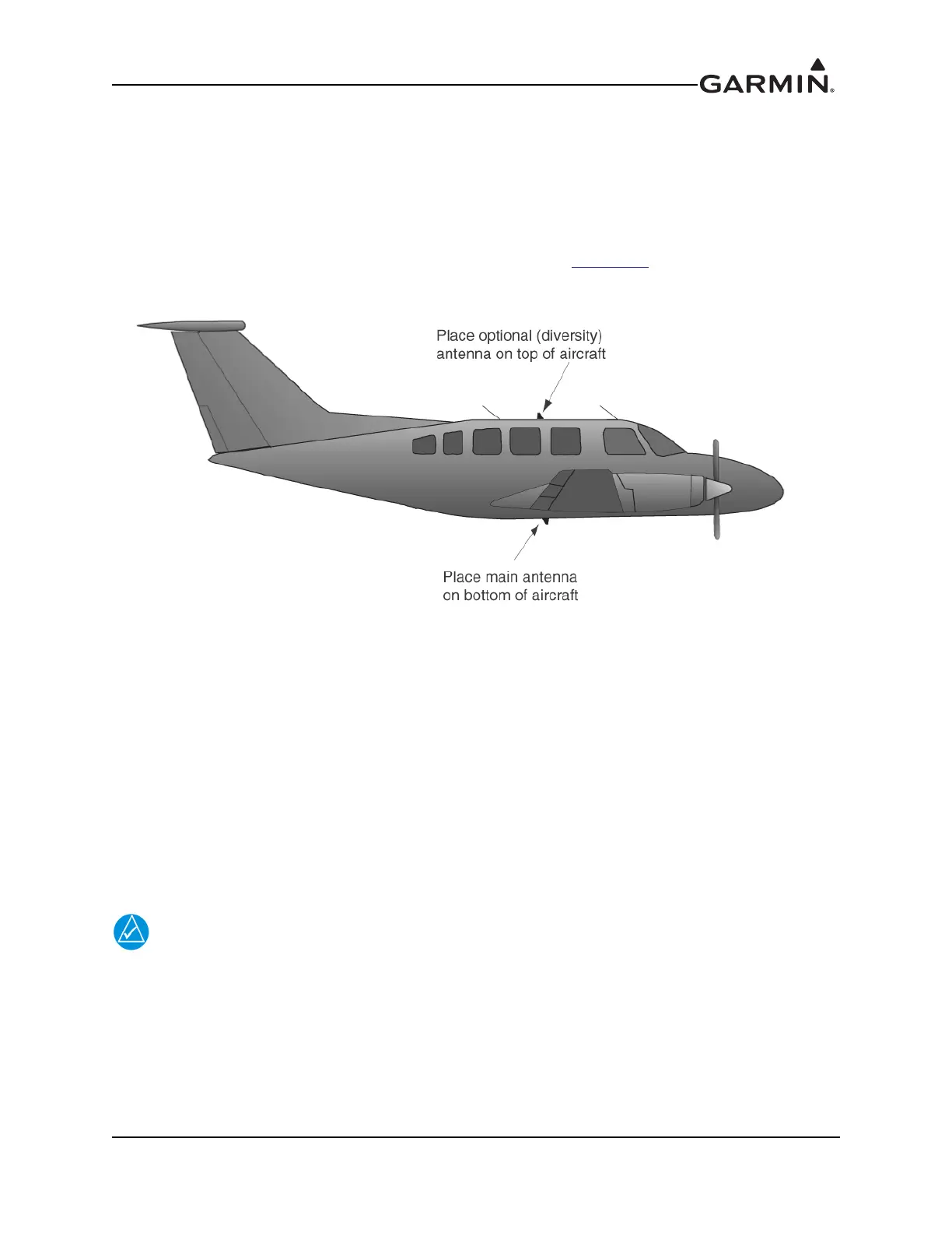
antenna. If a second (diversity) antenna is installed in the aircraft, considerations for its mounting should
be made as outlined in Figure 2-1. The antenna installation should be installed in accordance with
Advisory Circular AC 43.12-2A Chapter 3. Note that penetration of the pressure vessel on the pressurized
aircraft requires additional data not contained in this manual. (See
Section 2.6)
Figure 2-1 Antenna Installation Considerations
1. The antenna(s) (Garmin P/N 010-10160-00) should be mounted away from major protrusions,
such as engine(s), propeller(s), and antenna masts. It should also be as far as practical from
landing gear doors, access doors, or other openings that could effect its radiation pattern.
2. The main antenna should be mounted vertically on the bottom of the aircraft. The optional second
(diversity) antenna should be mounted vertically on top of the aircraft. Horizontal separation must
be no more than 7.6 meters (25 feet).
3. Avoid mounting the antenna within three feet of the ADF sense antenna or any other
communication antenna and six feet from the DME antenna.
4. To prevent RF interference, the antenna must be physically mounted a minimum distance of three
feet from the GTX 330.
If the antenna is being installed on a composite aircraft, ground planes must be
considered. Conductive wire mesh, radials, or thin aluminum sheets embedded in the
composite material provide the proper ground plane allowing the antenna pattern (gain)
to be maximized for optimum transponder performance.
2.4.2 Antenna Installation
Install the antenna according to the antenna manufacturer’s instructions and FAA Advisory Circulars
AC 43.13-1B and AC 43.13-2B.
 Loading...