GTX 330/330D Installation Manual 190-00207-02
Page 4-8 Rev. U
a modem. An ADLP performs functions requiring sending and/or receiving data from ground sensors via
Mode S interrogations and replies.
The GTX 330 is currently FAA approved to display TIS traffic information on Garmin 400/
500 Series, GNS 480 (CNX80), GMX 200, GTN 6XX/7XX, and MX20 products only.
4.6.1 RS-232 Input/Output
The RS-232 outputs conform to EIA Standard RS-232C with an output voltage swing of at least ±5 V
when driving a standard RS-232 load. Refer to
Figure 4-3, Figure D-2, Figure D-3, Figure D-5,
Figure D-6, Figure D-7 and Figure D-8 for RS-232 serial data interconnect and to Section 5.2.10 and
Section 5.2.22 for RS-232 serial data configuration.
When connecting two GTX 330 transponders to a GPS, the unit can only receive RS-232 serial data from
one unit at a time. Use a DPDT switch for connecting both serial data and External Standby Select. Refer
to
Figure D-9, Sheets 2 and 3.
4.6.2 RS-232 Input/Output, Software Update Connections
When the GTX 330 is installed in an aircraft an optional RS-232 serial data connector should be installed
in the aircraft for future software upgrades, negating the need to remove the transponder from the aircraft
panel. The connector can be mounted anywhere convenient for access, such as under the instrument panel,
on a remote avionics shelf or in the instrument panel itself. Be sure to label the connector for Software
Update. Do not include the Test Mode Select switch in the aircraft. See
Figure 4-3 for software update
connections.
If the GTX 330 installation interfaces with a GNS 480 (CNX80) in the aircraft, the GNS 480 (CNX80)
must be turned off during GTX 330 software upload, due to loading of RS-232 port 1.
Software versions prior to 6.00 should not be loaded onto GTX 330 w/ES and
GTX 330D w/ES units.
A software conflict could result if older revision software is loaded into some
GTX330(D) units, which could cause backlighting failures. Do not load any
software versions prior to 4.00 into the following units.
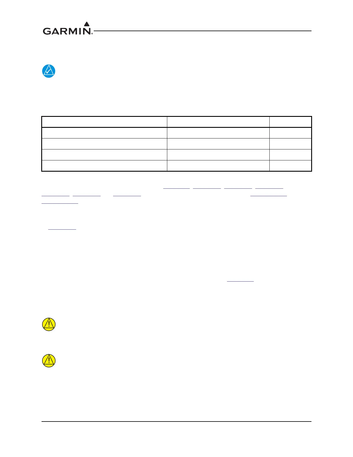
Table 4-8 RS-232 Pin Assignments
Pin Name Pin Number I/O
RS-232 OUT 1 23 Out
RS-232 IN 1 22 In
RS-232 OUT 2 25 Out
RS-232 IN 2 24 In
 Loading...